
MC34063ABD техническая спецификация
- Бренды: STMicroelectronics
- Скачать: MC34063ABD Техническое описание PDF
- Цена: расследование
- В наличии: 19,219
- Функция: Шаг вверх, шаг вниз
- Конфигурация вывода: Положительный или отрицательный
- Топология: Бак, Ускорение
- Упаковка: 8-SOIC (0,154, ширина 3,90 мм)


БЕСПЛАТНАЯ доставка для заказов свыше HK$250.00

Быстрый ответ, быстрая расценка

Быстрая отправка, никаких проблем после продажи

Оригинальный канал, гарантия подлинности продукции
MC34063ABD
If you’re working with DC/DC converters, you’ll want to check out the MC34063ABD—it’s a classic switching regulator chip that’s pretty versatile. It handles input voltages from 3V to 40V, perfect for all sorts of projects. You can use it to set up boost (step-up), buck (step-down), or even inverted voltage setups, which covers most scenarios you’ll face.
Inside, it’s got a robust transistor capable of driving external power transistors, giving you up to 1.5A output current easily. Plus, its standby current is super low—just around 4mA—helping you save energy and reduce heat. With its built-in oscillator at 100kHz, there’s no need for an external one, keeping your design simpler. PWM control ensures efficient voltage regulation, essential for battery-powered projects. The chip also includes built-in current limiting for safety, and it performs reliably across industrial-grade temperature ranges, from -40°C to 85°C.
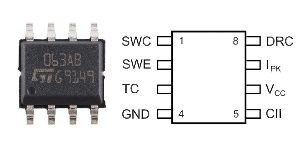
MC34063ABD Pinout

Here’s the pinout of the MC34063ABD in table format:
| Номер контакта | Имя пин-кода | Описание |
|---|---|---|
| 1 | Switch Emitter | Emitter terminal of internal power transistor |
| 2 | Switch Collector | Collector terminal for internal transistor; connects to external inductor or diode |
| 3 | Timing Capacitor (CT) | Connect capacitor to set oscillator frequency |
| 4 | Земля | Ground reference pin |
| 5 | Comparator Inverting Input | Feedback voltage input for voltage regulation |
| 6 | Vcc | Chip power supply (operating range: 3V–40V) |
| 7 | Ipk Sense | Current limit sensing pin for overcurrent protection |
| 8 | Driver Collector | Collector of internal driver transistor; connects to external power transistor |
Pinout Usage and Precautions:
-
Vcc Pin (Pin 6): This is the chip’s main power input, so make sure your voltage stays steady between 3V and 40V. Going beyond that range can damage your chip.
-
Timing Capacitor (CT, Pin 3): The capacitor you hook up here controls your switching frequency. Pick a capacitor size that matches the frequency you need—this will help your circuit run smoothly.
-
Ipk Sense (Pin 7): Use this pin for setting current limits. Add the right resistor here, and it’ll protect your circuit from any overloads by keeping current under control.
-
Feedback Input (Pin 5): This pin needs a stable voltage reference. Set up a reliable feedback loop here to keep your voltage regulation accurate.
-
Switch Pins (Pins 1 & 2): These pins carry high currents, so design your PCB traces short and wide to minimize resistance and avoid overheating.
MC34063ABD Equivalent


Here is a table comparing equivalent models for the MC34063ABD in the same package:
| Parameter | MC34063ABD | ТЛ494 | SG3525 | L4981 |
|---|---|---|---|---|
| Упаковка | ДИП-8 | ДИП-8 | ДИП-8 | ДИП-8 |
| Input Voltage Range | 3V – 40V | 8V – 40V | 8V – 40V | 6V – 40V |
| Output Voltage | Adjustable (up to 40V) | Adjustable (up to 40V) | Adjustable (up to 40V) | Adjustable (up to 40V) |
| Output Current | 1,5А | 1А | 1А | 2А |
| Switching Frequency | 100кГц | 100кГц | 100кГц | 300kHz |
| Internal Oscillator | Да | Да | Да | Да |
| Current Mode Control | Нет | Да | Да | Да |
| Integrated Features | Regulator, Boost Converter, Inverter | Pulse-width modulation | Pulse-width modulation | Pulse-width modulation |
If you’re looking for good alternatives to the MC34063ABD, you might want to check out the TL494 and SG3525. Both are solid choices, offering similar functionality and good voltage and current capabilities. They’re especially handy if you need to generate PWM signals for your DC-DC conversion projects.
Another good option is the L4981. It steps things up a bit by providing a higher output current of up to 2A, and it can handle higher switching frequencies around 300 kHz. This makes it a great pick if you’re aiming for better efficiency or need faster switching in your design.
Remember though, even if these alternatives come in the same DIP-8 package, you should always double-check your project’s specific needs—things like voltage, current, and frequency—to make sure everything fits perfectly together.
mc34063 step up converter
If you’re working with the MC34063 step-up converter, here’s a quick rundown on how it operates:
-
Energy Storage (Switch On): When the switch is on, current flows through the inductor, which stores energy in the form of a magnetic field.
-
Energy Transfer (Switch Off): Once the switch turns off, the energy stored in the inductor increases the voltage across it. The diode ensures the current flows only to the output capacitor and doesn’t go back into the input.
-
Boosting Output Voltage: The energy from the inductor raises the output voltage, which is higher than the input. The capacitor smooths out the voltage to make it more stable.
-
Controlling the Output: The output voltage is adjusted by changing the duty cycle (the time the switch is on). A higher duty cycle means a higher output voltage.
mc34063 boost converter circuit

This step-up converter circuit boosts a lower input voltage to a higher, more stable output voltage. It achieves this through a feedback control loop that stabilizes the output voltage. The MC34063 is commonly used in applications that need a low-cost solution for boosting voltage in circuits, especially in devices like battery-powered electronics.
Operation Flow:
1. Energy Storage (Switch On):
When you turn the switch on in the MC34063 circuit, current flows through the inductor (L1). This current stores energy in the form of a magnetic field in the inductor.
2. Energy Transfer (Switch Off):
Once the switch turns off, the energy stored in the inductor causes the voltage across it to rise. This higher voltage is passed through a diode (D1) and directed to the output capacitor (C2), which boosts the output voltage above the input.
3. Output Voltage Adjustment (Feedback Control):
The output voltage is stabilized by the feedback loop, which uses resistors (R1 and R2) to control the output. The MC34063’s internal feedback system keeps the voltage steady, making adjustments to maintain a consistent output.
4. Smoothing the Output (Filter Capacitor):
To reduce ripple and ensure a smooth, stable DC output, the output capacitor (C3) helps filter the voltage, providing clean, steady power to your circuit.
mc34063 calculator tool
How the MC34063 Calculator Tool Works:
-
Choose Your Mode: You’ll start by deciding if you want the converter to act as a boost, buck, or inverter. Once you choose, the calculator adjusts the component values accordingly.
-
Component Suggestions: After entering the input/output voltage and current, the tool will suggest the right components (like inductors, capacitors, resistors) to make sure everything works smoothly and safely.
-
Feedback Control: This tool also ensures that the feedback loop is correctly set up, which is key for keeping your output voltage stable and regulated.
Why You’ll Love the Tool:
-
The MC34063 calculator tool makes the whole process of designing a power conversion circuit a lot easier. It does all the calculations and suggests the right components without you having to do it manually.
-
This tool helps you create efficient, stable, and safe circuits. No need to worry about figuring out each component’s value on your own.
-
It’s perfect for anyone who needs to quickly design boost converters, buck converters, or inverters using the MC34063 IC.
mc34063 power supply design & mc34063 smps design
When designing a power supply with the MC34063, there are a few key features to keep in mind. The IC supports an input voltage range from 3V to 40V, making it a great choice for various power sources, including battery-powered systems. You can adjust the output voltage based on whether you’re using the IC as a boost, buck, or inverter converter, and you can keep it regulated using external resistors. With the ability to provide up to 1.5A of output current, the MC34063 is suitable for many low- to medium-power loads. Its efficiency is typically between 70% and 80%, which works well for low-power applications but may not be as high as some modern switching regulators found in higher-power designs.
To design your power supply, start by determining your input and output requirements, such as choosing an input voltage (e.g., 5V) and deciding on your desired output voltage (e.g., 12V) and current. Then, select an inductor, typically ranging from 100µH to 220µH, ensuring it has a current rating higher than the output current. A Schottky diode like the 1N5819, along with capacitors (100µF to 470µF), will help filter and smooth the input and output voltages. To set the output voltage, you’ll use a simple formula with feedback resistors:
where R1 and R2 are the feedback resistors. Finally, adding a current sense resistor will help with overcurrent protection, ensuring your design remains safe.
mc34063 vs lm2596

mc34063 vs lm2596
Here’s a comparison table between the MC34063 and the LM2596, focusing on their key parameters:
| Parameter | MC34063 | LM2596 |
|---|---|---|
| Converter Type | Boost, Buck, Inverter | Buck Converter |
| Input Voltage Range | 3V to 40V | 4.5V to 40V |
| Диапазон выходного напряжения | Adjustable (depends on external resistors) | Adjustable (1.23V to 37V) |
| Output Current | Up to 1.5A | Up to 3A |
| Efficiency | 70-80% | 80-90% |
| Switching Frequency | 100кГц | 150kHz |
| Internal Switch | NPN-транзистор | Internal MOSFET |
| Output Ripple | Higher ripple due to discrete design | Lower ripple, better output stability |
| Тип упаковки | Typically 8-pin DIP or 8-pin SOIC | Typically 5-pin TO-220 or 5-pin TO-263 |
| Overcurrent Protection | No built-in protection | Built-in overcurrent protection |
| Расходы | Lower | Higher |
If you’re thinking about swapping out the MC34063 for the LM2596, here are a few things to keep in mind. The LM2596 is a great choice if you need something for high-current applications. It also tends to offer better efficiency and stability compared to the MC34063. However, the LM2596 only works in the buck configuration, meaning it can only step down voltage. So, if you need a boost or inverter functionality in your design, the MC34063 might still be the better option for you. One more thing to consider is that the LM2596 usually comes at a higher cost, since it includes more integrated features.
mc34063 smps design
Why the MC34063 is Great:
-
Low Cost: If you’re on a budget, the MC34063 is a great option. It’s inexpensive and easy to find, making it perfect for low-cost designs.
-
Versatility: You can configure it in different ways – as a boost, buck, or inverter converter. This flexibility makes it a solid choice for a variety of projects.
-
Compact Design: The MC34063 comes with most of the components you need built-in, which means less complexity and a smaller circuit overall.
Some Limitations to Keep in Mind:
-
Efficiency: The MC34063 is efficient for low-power applications, but it’s not as efficient as newer regulators like the LM2596, which can hit efficiency levels of 80-90%.
-
Выходной ток: It can provide up to 1.5A of output current. While this is fine for many projects, it may not be enough for higher-power applications.
mc34063 application circuit
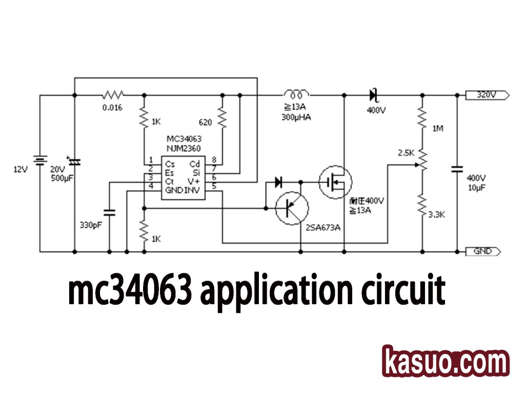
Here’s how the circuit works:
-
Power Supply:
First off, the circuit is powered by a 12V DC source. This is your starting point. -
Switching Control:
The MC34063 IC takes care of controlling the internal switch (usually a transistor). It turns the switch on and off rapidly, which controls the flow of current in the circuit. -
Energy Storage:
When the switch is off, the inductor (L) stores energy as current flows through it. This is the energy that’ll get released later. -
Energy Release:
When the switch turns back on, the stored energy in the inductor is released through the diode (D) to the load. This also boosts the voltage as the energy flows. This on-off switching process happens frequently. -
Voltage Boosting:
Thanks to the action of the inductor and the diode, the input voltage (12V) is stepped up to about 320V, which is perfect for powering higher-voltage devices. -
Filtering and Stable Output:
Capacitors at the output smooth out the voltage, reducing ripple and ensuring a stable, high-voltage output. -
Feedback Regulation:
The feedback pin of the MC34063 keeps an eye on the voltage changes. It adjusts the switching frequency to keep the output voltage right where it needs to be.
So, to sum it up: this whole process relies on rapid switching and the combined work of the inductor and diode to step up the voltage. It’s ideal for powering applications that need higher voltage.
Больше похожего

74HCT08PW
Нексерия

74AHC1G02GV
Нексерия

CD4081BF3A
Техасские инструменты
74AHCT1G00GW
Нексерия
74AHCT1G08GW
Нексерия
TC4001BP
Тошиба
CD4011BF3A
Техасские инструменты
74AHCT14PW
Нексерия
TC7S02FU
Тошиба

74LVC00AD
Нексерия
74HC10D
Нексерия
74AHCT541PW
Нексерия
Также добавить в корзину
SDINBDG4-32G-XA
СанДиск

XCKU060-2FFVA1156E
AMD Xilinx

AM1808BZWTD4
Техасские инструменты
STMPS2171STR
STMicroelectronics

STM32F401CCY6TR
STMicroelectronics

ATMEGA168V-10MU
Технология микрочипов

MCP3008-I/SL
Технология микрочипов
LT1910ES8
Аналоговые Устройства
ADP3330ART-3.3
Аналоговые Устройства

LM2941LD/NOPB
Национальный полупроводник

LT3045EMSE#PBF
Аналоговые Устройства Inc.

NCP3163BPWR2G
онсеми
Сопутствующие товары
74HCT08PW
Нексерия
74AHC1G02GV
Нексерия
CD4081BF3A
Техасские инструменты
74AHCT1G00GW
Нексерия
74AHCT1G08GW
Нексерия
TC4001BP
Тошиба
CD4011BF3A
Техасские инструменты
74AHCT14PW
Нексерия
TC7S02FU
Тошиба
74LVC00AD
Нексерия
74HC10D
Нексерия
74AHCT541PW
Нексерия
74HC132PW
Нексерия
74HC1G04GV
Нексерия
74AHC1G04GW
Нексерия
74AHC1GU04GW
Нексерия
74HC27D
Нексерия
TC7S00FU
Тошиба
74LVC00APW
Нексерия
74HCT86D
Нексерия
74LVC1G11GW
Нексерия
HEF4071BT
Нексерия

74LVC1G02GV
Нексерия
HEF4070BT
Нексерия

MC14093BCP
онсеми
74HC32PW
Нексерия
74HC1G08GW
Нексерия
74AHC00D
Нексерия
74LVC1G86GW
Нексерия

HEF4093BP
NXP Полупроводники
Пожалуйста, отправьте запрос предложения, мы ответим немедленно.
