ADRF5730BCCZN технический паспорт, цена | pdf
- Бренды: Аналоговые Устройства Inc.
- Скачать: ADRF5730BCCZN Datasheet PDF
- Цена: расследование
- В наличии: 11,885
- Attenuation Value: 0.5dB ~ 31.5dB
- Диапазон частот: 100 MHz ~ 40 GHz
- Power(Watts): 500mW
- Упаковка: Strip

ADRF5730BCCZN-R7 Datasheet
Download Spanish PDF: ADRF5730BCCZN Datasheet PDF
ADRF5730BCCZN Pinout Equivalent Circuit
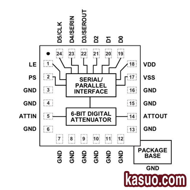
The adrf5730bcczn is a 6-bit silicon digital attenuator from Analog Devices that provides 31.5dB of attenuation control in 0.5dB steps. The chip can operate in a frequency range of 100 MHz to 40 GHz and offers better than 4.8dB insertion loss and excellent attenuation accuracy. The port design uses a conventional 50Ω characteristic impedance matching. For wideband applications, impedance matching on the RF transmission signal line can further reduce signal energy loss at high frequencies. And it can provide an SPI interface to communicate with external devices.
Pin Definition:
| PIN | NAME | FUNCTION |
|---|---|---|
| 1 | LE | Lock enable input. |
| 2 | ПС | Select input for parallel or serial control interface. |
| 3, 4, 6–13, 15, 16 | GND | Grounding pin. |
| 5 | ATTIN | Attenuator input. This pin is DC coupled to 0V and has an AC impedance matching of 50 Ω. |
| 14 | ATTOUT | Attenuator output. This pin is DC coupled to 0V and has an AC impedance matching of 50 Ω. |
| 17 | VSS | Negative power input. |
| 18 | VDD | Positive power input. |
| 19 | D0 | Parallel control input with 0.5 dB attenuator bit. |
| 20 | D1 | 1 dB attenuator bit parallel control. |
| 21 | D2 | Parallel control input for 2 dB attenuator bits. |
| 22 | D3/SEROUT | 4 dB attenuator bit parallel control input (D3) or serial data output (SEROUT). |
| 23 | D4/SERIN | 8 dB attenuator bit parallel control input (D4) or serial data input (SERIN). |
| 24 | D5/CLK | 16 dB attenuator bit parallel control input (D5) or serial clock input (CLK). |
| EPAD | bonding pad | The exposed solder pad must be connected to a DC ground. |
Alternative model options
In practical applications, it may be necessary to find an alternative selection of ADRF5730BCCZN for some reasons, but after searching, it is found that a completely suitable product may only be fully compliant with ADRF5730BCCZN, so when we select alternative models, we focus on similar products, such as upper substitution selection or lower substitution selection, and it is generally certain that it has not been replaced by selection, and some of the accuracy or area may be lost if the subordinate substitution selection is not yet selected; Overall, we need to make a trade-off. The main parameters to be considered in the selection are: 1. the working frequency range, 2. the compatibility of the power supply and the control signal, 3. the attenuation range, and 4. whether the package meets the requirements. Here are a few alternative replacements.
| Картина | Name | Frequency range | Matching impedance | Attenuation | Package |
|---|---|---|---|---|---|
 |
ADRF5716 | 0.1GHz~30GHz | 50Ω | 16dB ~ 48dB | VFLGA-20-EP |
 |
ADRF5730 | 100MHz~40GHz | 50Ω | 0.5dB~31.5 dB | VFLGA-24-EP |
 |
ADRF5731 | 100MHz~40GHz | 50Ω | 2dB~30dB | VFLGA-16-EP |
 |
ADRF5740BCCZN-R7 | 10MHz~60GHz | 50Ω | 2dB~22dB | VFLGA-16-EP |
Typical Applications

RF sampling structure is very important in the design of modern radio reception industry, and the choice of architecture has a great impact on the harmonic performance of the system, and there are two main methods: direct RF sampling and heterodyne converter. The disadvantages of heterodyne architecture compared with direct RF sampling are that the structure is complex, it is easy to generate harmonics, and it requires accurate design frequency planning, and the complex structure also leads to the high cost required. Therefore, the RF structure is more commonly used at present. The diagram shows a relatively simple RF structure, where the RF signal is received through the input port, then the signal is amplified by an amplifier and enters the filter to complete the band selection and clutter suppression (amplification and filtering should effectively improve the signal quality), and finally the RF signal is received by an analog-to-digital converter (ADC).
Больше похожего

NEO-F9P-15B
u-блокс

STA8100GA
STMicroelectronics

QPF4526TR13
Qorvo

QPF4656TR13
Qorvo

TQL9062
Qorvo

CMD241P4
Qorvo

CMD315C4
Qorvo
SKY77652-11
Skyworks Solutions Inc.

ADPA9007ACGZN
Аналоговые Устройства Inc.

SKY85006-11
Skyworks Solutions Inc.

TGA2578-CP
Qorvo

TGA2575
Qorvo
Также добавить в корзину

SKY66288-11
Skyworks Solutions Inc.

WF121-A-V2
Кремниевые Лаборатории
QPF4656TR13
Qorvo

TQP369184
Qorvo

HMC773LC3B
Аналоговые Устройства Inc.

ADT4-1WT+
Мини-схемы

PHA-13LN+
Мини-схемы
MP9487GN
JLCPCB Assembly

SPBT3.0DP2
STMicroelectronics
MAX96781GTN/V+T
JLCPCB Assembly

AP6275S
AMPAK Tech

NRF52810-QCAA-R
Nordic Semiconductor ASA
NEO-F9P-15B
u-блокс
STA8100GA
STMicroelectronics
QPF4526TR13
Qorvo
QPF4656TR13
Qorvo
TQL9062
Qorvo
CMD241P4
Qorvo
CMD315C4
Qorvo
SKY77652-11
Skyworks Solutions Inc.
ADPA9007ACGZN
Аналоговые Устройства Inc.
SKY85006-11
Skyworks Solutions Inc.