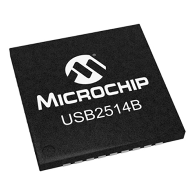
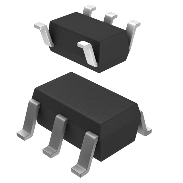
USB2514B-I/M2 datasheet & specs
- Protocol: USB
- Function: Hub Controller
- Interface: USB
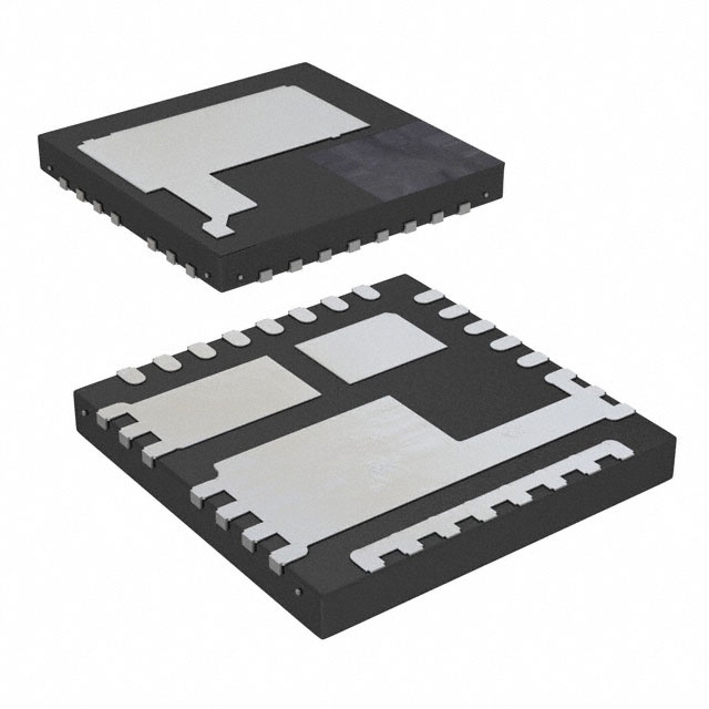
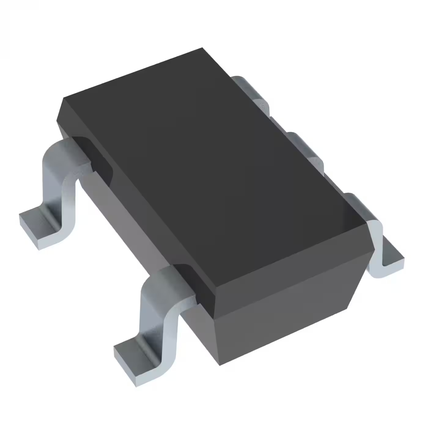
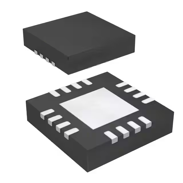
- Package: 36-VFQFN Exposed Pad

FREE delivery for orders over HK$250.00

Quick response, quick quotaton

Flash shipment,no worries after sales

Original channel,guarantee of the authentic products
USB2514B-I/M2
If you’re building a USB hub system, the USB2514B-I/M2 from Microchip is worth checking out. It’s a powerful yet low-power 4-port USB 2.0 Hi-Speed controller, ideal for embedded systems, consumer electronics, or industrial projects.
One cool thing about this chip is it uses multiple transaction translators (MTT), meaning your connected devices won’t slow each other down. It also offers flexible port mapping (PortMap) and PHYBoost tech to adjust signal strength, ensuring stable connections.
You can run it on 3.0–3.6 volts, and it’ll handle tough industrial conditions (-40°C to +85°C). Plus, it’s compact (36-pin SQFN, 6x6mm) and supports USB Battery Charging spec 1.1, so your devices can charge right through the hub.
usb2514b-i/m2 pinout

Here’s the pinout for the USB2514B-I/M2 chip in a concise table format:
| Pin No. | Pin Name | Type | Description |
|---|---|---|---|
| 1 | USBDM_DN1 | I/O | USB D- signal for downstream port 1 |
| 2 | USBDP_DN1 | I/O | USB D+ signal for downstream port 1 |
| 3 | USBDM_DN2 | I/O | USB D- signal for downstream port 2 |
| 4 | USBDP_DN2 | I/O | USB D+ signal for downstream port 2 |
| 5 | VDD33 | Power | 3.3V digital power input |
| 6 | USBDM_DN3 | I/O | USB D- signal for downstream port 3 |
| 7 | USBDP_DN3 | I/O | USB D+ signal for downstream port 3 |
| 8 | USBDM_DN4 | I/O | USB D- signal for downstream port 4 |
| 9 | USBDP_DN4 | I/O | USB D+ signal for downstream port 4 |
| 10 | VDDA33 | Power | 3.3V analog power input |
| 11 | TEST | Input | Test pin, ground during normal operation |
| 12 | PRTPWR1/BC_EN1 | Output | Port 1 power control or battery charging enable |
| 13 | OCS_N1 | Input | Port 1 overcurrent sense (active low) |
| 14 | CRFILT | Analog | Internal regulator filter capacitor connection |
| 15 | VDD33 | Power | 3.3V digital power input |
| 16 | PRTPWR2/BC_EN2 | Output | Port 2 power control or battery charging enable |
| 17 | OCS_N2 | Input | Port 2 overcurrent sense (active low) |
| 18 | PRTPWR3/BC_EN3 | Output | Port 3 power control or battery charging enable |
| 19 | OCS_N3 | Input | Port 3 overcurrent sense (active low) |
| 20 | PRTPWR4/BC_EN4 | Output | Port 4 power control or battery charging enable |
| 21 | OCS_N4 | Input | Port 4 overcurrent sense (active low) |
| 22 | NON_REM1 | Input | Non-removable device indication for port 2 |
| 23 | LED_A3_N/PRT_SWP3 | I/O | Port 3 LED indicator or port swap configuration |
| 24 | CFG_SEL0 | Input | Configuration select (EEPROM/SMBus option) |
| 25 | CFG_SEL1 | Input | Configuration select (EEPROM/SMBus option) |
| 26 | SUSP_IND/LOCAL_PWR/NON_REM0 | I/O | Suspend indicator, local power sense, or port 1 non-removable |
| 27 | VBUS_DET | Input | Upstream VBUS detection |
| 28 | NON_REM0 | Input | Non-removable device indication for port 1 |
| 29 | VDDA33 | Power | 3.3V analog power input |
| 30 | USBDM_UP | I/O | Upstream USB D- signal |
| 31 | USBDP_UP | I/O | Upstream USB D+ signal |
| 32 | XTALOUT | Output | Crystal oscillator output |
| 33 | XTALIN/CLKIN | Input | Crystal oscillator input or external clock input |
| 34 | PLLFILT | Analog | PLL filter capacitor connection |
| 35 | RBIAS | Analog | Internal bias resistor connection |
| 36 | VDDA33 | Power | 3.3V analog power input |
| ePAD | GND | Ground | Ground connection (must connect to PCB ground plane) |
Pin Usage and Important Notes:
First, power it from a stable 3.3V supply and put small capacitors (about 0.1µF) near the power pins. Make sure the exposed pad underneath connects firmly to your PCB ground to reduce noise and heat.
Keep your USB differential lines (USBDP, USBDM) matched in impedance for clean signals.
For overcurrent protection, use the OCS_Nx pins (they activate low) connected to power switches with built-in detection—this keeps your setup safe.
Use PRTPWRx pins to control downstream power, hooking them to MOSFET drivers or power switches.
Set configuration with CFG_SEL0 and CFG_SEL1 pins depending on your needs—EEPROM or SMBus.
Lastly, connect XTALIN and XTALOUT to a 24 MHz crystal oscillator for accurate timing and USB compliance.
usb2514b-i/m2 equivalent
| Parameter | USB2514B-I/M2 (Original) | FE1.1 (Terminus) | TUSB8042A (TI) | FE18.1 (Terminus) |
|---|---|---|---|---|
| USB Standard | USB 2.0 Hi-Speed | USB 2.0 Hi-Speed | USB 3.2 Gen1 | USB 2.0 Hi-Speed |
| Downstream Ports | 4 | 4 | 4 | 4 |
| Multiple Transaction Translators (MTT | Supported | Supported | Supported | Supported |
| Operating Voltage | 3.0V ~ 3.6V | 5V (Built-in LDO) | 3.3V | 5V (Built-in LDO) |
| Typical Current | 70mA | 64~115mA | Not disclosed | Not disclosed |
| Operating Temperature | -40°C ~ +85°C | 0°C ~ +70°C | -40°C ~ +85°C | Not disclosed |
| Package Type | 36-SQFN (6x6mm) | 48-QFN (6x6mm) | 64-QFN (9x9mm) | 48-QFN (6x6mm) |
| Battery Charging Support | Yes (BC 1.1) | No | Yes (Multi-mode) | Yes (BC 1.2) |
| Configuration Options | I²C EEPROM or SMBus | Fixed configuration | EEPROM or I²C | Fixed configuration |
| Manufacturer | Microchip | Terminus | Texas Instruments | Terminus |
If you’re thinking about replacing your USB2514B-I/M2 controller, keep in mind that FE1.1 and FE18.1 have slightly larger 48-pin QFN packages, and the TUSB8042A is even bigger at 64 pins, which means you’ll need to redesign your PCB quite a bit. Performance-wise, TUSB8042A could be a good option if you’re planning for faster USB 3.2 Gen1 speeds (5Gbps), but FE1.1 and FE18.1 closely match your current USB 2.0 setup. Also, FE1.1 and FE18.1 simplify your power design with built-in 5V regulators but don’t offer the flexible EEPROM or SMBus configuration you get with USB2514B. Lastly, always confirm the new chip meets your operating temperature requirements, especially for industrial or automotive applications.
usb2514b-i/m2 hub circuit schematic & usb2514b-i/m2 hub ic reference design

When you’re setting up this USB hub circuit, here’s what you should keep in mind:
For the USB connections, your upstream port (connected to the host) uses pins 1 and 30 for the USBDP and USBDM lines. You also have four downstream ports (DN1 to DN4) for hooking up devices or expansion connectors.
Make sure to supply a stable 3.3V power to pins VDD33 and VDDA33. I’d suggest placing some decoupling capacitors nearby to keep your voltage clean and stable.
If you need to store hub configurations or device descriptors, connect pins 28 and 29 to an external EEPROM like the 24LC02B.
Don’t skip the crystal oscillator—connect pins 32 and 33 to an external crystal to ensure accurate USB timing.
For port management, use the DIS pin to disable ports selectively and the PRTPWR pins to manage power distribution effectively.
Finally, connect the OCS pin to your overcurrent protection circuit. This protects both the chip and your connected devices from damage if something goes wrong.
usb2514b-i/m2 embedded usb wiring

If you’re thinking about designing your own embedded USB hub, here’s a simple example you can follow using Microchip’s USB2514B-I/M2 chip. On the left side of your circuit, you’ll connect it directly to your USB host—this is where it gets its main power (V) and the USB data signals (D+ and D-). Then, the chip splits that single connection into multiple USB ports (DN1 through DN4) on the right, giving you plenty of expansion options. To keep things safe and reliable, remember to put ESD protection components on each downstream data line—this keeps static electricity from messing things up. Also, it’s important to add a few decoupling capacitors, like a 0.1 µF and a 10 µF, near your chip to stabilize the power supply. With these details sorted out, you’ll have yourself a stable, reliable USB hub ready for action.
usb2514b-i/m2 usb 2.0 controller ic
If you’re working on projects like embedded systems, docking stations, industrial automation, automotive infotainment setups, or even medical devices, the USB2514B-I/M2 controller could be exactly what you need. Basically, it lets you take one USB port and turn it into four, giving you stable, high-speed connections. It also helps manage power efficiently, which is especially useful if you’re dealing with tough, industrial-level environments. This way, your devices can communicate quickly and reliably without running into connection or power issues.
usb2514b-i/m2 multiport usb circuit

When you’re setting up your USB hub, first connect the hub chip to your host device (like your computer) through pins 30 and 31 for USB data signals (D+ and D-). Pin 28 (VBUS_DET) checks if your host is providing power. The chip then splits your single host connection into four downstream USB ports, each with its own 5V power line and built-in overcurrent protection for safety. Use a stable external 24MHz crystal oscillator to keep things running smoothly, and power the chip with a clean 3.3V supply along with filtering capacitors. You can also configure the chip easily through dedicated pins and monitor status with LEDs.
usb2514b-i/m2 i2c configuration example
If you’re setting up the USB2514B-I/M2 chip and want it to automatically configure itself, here’s a handy way: just use an external EEPROM like the common 24LC02. Basically, you’ll connect the chip’s I²C pins—SCL (pin 26) and SDA (pin 27)—to the matching pins on your EEPROM. Inside the EEPROM, you’ll store important setup info like Vendor ID, Product ID, port configurations, and power management options. Then, every time your USB2514B powers up, it’ll automatically read this data and configure itself exactly how you want it—no extra microcontroller needed. This makes your design cleaner and saves you time.
