
TP4057 schematic & datasheet | vs TP4056 EVVO
- Battery Chemistry: Lithium Ion
- Charge Current - Max: 500mA
- Current - Charging: Constant - Programmable
- Package: SOT-23-6


FREE delivery for orders over HK$250.00

Quick response, quick quotaton

Flash shipment,no worries after sales

Original channel,guarantee of the authentic products
TP4056 vs. TP4057 Li-Ion Battery Charging Boards Quick Comparison 18650 And More
TP4056 vs TP4057
Differences between TP4056 VS TP4057 in Pin Configuration and Application Circuits:
| Comparison Item | TP4056 (SOP-8 Package) | TP4057 (SOT23-6 Package) |
|---|---|---|
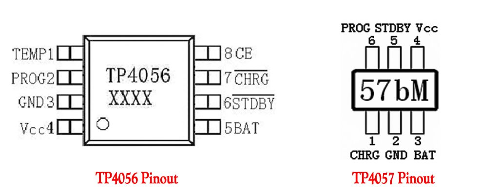
| Chip Pins | 8-pin Package ① TEMP (Temperature sensing input) ② PROG (Charge current setting) ③ GND (Ground) ④ VCC (Power input) ⑤ BAT (Battery positive terminal) ⑥ STDBY (Charge complete indicator) ⑦ CHRG (Charging status indicator) ⑧ CE (Chip enable control) |
6-pin Package ① CHRG (Charging status indicator) ② GND (Ground) ③ BAT (Battery positive terminal) ④ VCC (Power input) ⑤ STDBY (Charge complete indicator) ⑥ PROG (Charge current setting) |
| Pin Differences Summary | Includes additional TEMP pin for temperature sensing. CE pin available for external control to enable/disable the chip. |
No TEMP pin for temperature sensing. No CE pin; chip is always enabled. |
| Application Circuit Differences | More complex; supports NTC thermistor (connected to TEMP pin) for battery temperature monitoring. Includes additional enable/disable functionality (via CE pin). |
Simpler; no temperature monitoring function, ideal for compact and space-constrained designs. |
| Maximum Charge Current | Up to 1A | Recommended maximum of 500mA |
| Charge Current Setting Formula | ICHG = 1200 / RPROG | ICHG = 1000 / RPROG |
| Typical Rprog Selection | 1.2kΩ resistor for 1A charge current | 2kΩ resistor for approximately 500mA charge current |
TP4056 VS TP4057 peripheral circuits, specific pin connections, and functions of each external component:

| Component | TP4056 Peripheral Circuit (Left Diagram) | TP4057 Peripheral Circuit (Right Diagram) |
|---|---|---|
| Input Current-Limiting Resistor | RL1 = 0.4Ω, connected to VCC (Pin 4) Limits input surge current to protect the chip from potential damage. |
Not Present (5V input directly to VCC, Pin 4) |
| Input Filter Capacitor | C1 = 10μF, connected between VCC (Pin 4) and GND (Pin 3) Reduces ripple noise and stabilizes input voltage. |
1μF, connected between VCC (Pin 4) and GND (Pin 2) Basic noise filtering for compact designs. |
| Output Filter Capacitor | C2 = 10μF, connected between BAT (Pin 5) and GND (Pin 3) Ensures stable battery voltage and reduces output ripple. |
10μF, connected between BAT (Pin 3) and GND (Pin 2) Same function: stabilizes battery voltage during charging. |
| Charging Status LEDs and Resistors | Two LEDs: – D1 with RL2=1kΩ resistor, connected to CHRG (Pin 7): indicates charging status. – D2 with RL3=1kΩ resistor, connected to STDBY (Pin 6): indicates charging completed or standby mode. |
Single LED with 1kΩ resistor connected to CHRG (Pin 1) Simplified indicator for charging status only. |
| Charge Current Setting Resistor (Rprog) | Rprog resistor connected between PROG (Pin 2) and GND (Pin 3) Determines charging current, e.g., 1.2kΩ sets approx. 1A. |
Rprog = 1.66kΩ, connected between PROG (Pin 6) and GND (Pin 2) Sets charging current around 600mA. |
| Temperature Sensing Resistor (NTC) | RL4 (10kΩ or NTC thermistor) connected between TEMP (Pin 1) and GND (Pin 3) Monitors battery temperature for enhanced safety during charging. |
No Temperature Sensing Capability |
| Chip Enable Control (CE Pin) | CE (Pin 8): external control signal Allows enabling or disabling the chip. |
No Enable Control Pin Chip always enabled by default. |
TP4056 Peripheral Circuit (Left Diagram):
1. More complex; includes temperature sensing, dual LED status indicators, input current limiting, and enable control.
2. Ideal for applications requiring higher safety and additional functionality.
TP4057 Peripheral Circuit (Right Diagram):
3. Simpler design; fewer external components, no temperature monitoring, single LED indicator, and always-on operation.
4. Ideal for compact, low-current, straightforward applications.
More Like This

CBTL06GP213EE
NXP Semiconductors

MAX458EPL
Analog Devices / Maxim Integrated
ADG5412FBCPZ
Analog Devices
ADG5412BFBCPZ
Analog Devices
ADG854BCPZ
Analog Devices
DG187AA
Vishay / Siliconix

74LVC1G66GV
Nexperia
FSA2275A
onsemi
TC4066BP
Toshiba
74LVC2G66DP
Nexperia
74LVC1G66GW
Nexperia
ADG1414BCPZ
Analog Devices
Also Add to Cart

TPS63021DSJR
Texas Instruments

DSP56311VL150
NXP USA Inc.

DS26C32ATM
Texas Instruments
THVD1451DR
Texas Instruments

STM32F446ZEJ6TR
STMicroelectronics
MCP3221A6T-E/OT
Microchip Technology

NCP13992ACDR2G
onsemi

STM32H563ZIT6
STMicroelectronics

74HC259D
Toshiba Semiconductor and Storage

LT1763CS8-3.3#TRPBF
Analog Devices Inc.

LTC1387ISW
Analog Devices

XCKU5P-2FFVB676I
AMD Xilinx
Related Products
CBTL06GP213EE
NXP Semiconductors
MAX458EPL
Analog Devices / Maxim Integrated
ADG5412FBCPZ
Analog Devices
ADG5412BFBCPZ
Analog Devices
ADG854BCPZ
Analog Devices
DG187AA
Vishay / Siliconix
74LVC1G66GV
Nexperia
FSA2275A
onsemi
TC4066BP
Toshiba
74LVC2G66DP
Nexperia
74LVC1G66GW
Nexperia
ADG1414BCPZ
Analog Devices

MAX4649EKA
Analog Devices / Maxim Integrated
74HC1G66GW
Nexperia
74LVC4066PW
Nexperia
ADG702BRTZ
Analog Devices
ADG701BRTZ
Analog Devices

ADG1219BRJZ
Analog Devices

74HCT4066D
Nexperia
ADG819BRTZ
Analog Devices
HEF4066BT
Nexperia

74HC4066PW
Nexperia
ADG1436YCPZ
Analog Devices
74HC1G66GV
Nexperia
ADG802BRTZ
Analog Devices
CLC018AJVJQ
Texas Instruments
HEF4014BT
Nexperia

74HCT165D
Nexperia

MC14094BCP
onsemi
74HCT164D
Nexperia
Please send RFQ , we will respond immediately.
