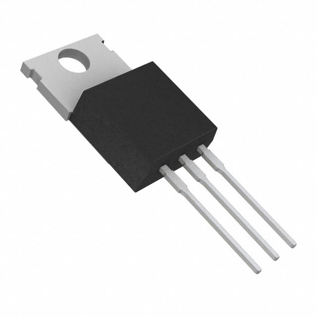
TIP41C Transistor | Datasheet | Pinout | Amplifier Circuit Fairchild Semiconductor
- Transistor Type: NPN
- Current-Collector(Ic)(Max): 6 A
- Voltage-Collector Emitter Breakdown (Max): 100 V
- Package: TO-220-3
TIP41C circuit

TIP41C Pinout Diagram
The TIP41C is an NPN type transistor that can be used in power amplification and switching circuits. The collector breakdown voltage is 100V, which can be applied in circuit designs with higher voltage tolerance; the collector cut-off current is 0.7mA, indicating a very low leakage current and a high conversion rate. It has features such as high current load capability and fast response. It can be used as a complementary symmetrical tube with TIP42CPNP tube.
The TIP41C NPN power transistor works as follows:
1. Amplifying current: When a positive voltage is applied to the base of the transistor, it starts conducting. This causes current to flow through the base and into the emitter of the transistor. This current is amplified and then flows through the collector of the transistor.
2. Control current: When a voltage is applied to the base of the transistor, it controls the flow of current. If the voltage is too low, the current will not be able to flow, and if the voltage is too high, the current will be overloaded.
3、Amplify voltage: When current flows through the transistor, the voltage is also amplified. In this way, the transistor can be used to amplify voltage.

Amplifier Circuit Diagram
The P3 interface in the figure is connected to the relay. When the optocoupler is open, the S8550 must be cut off, so the TIP41C is also in the cut-off state, so it can not supply power to the relay; when the optocoupler conductive, the S8550 is also conductive, the TIP41C base receives a trigger signal, and then conductive, the current flows through the relay, the relay closure. This side needs to pay attention to the two base resistors R11 and R14, if the drive current is not enough S8550 and TIP41C conduction, you can choose to reduce the resistance value of the two resistors (generally not recommended to remove, to prevent burning through the transistor). In order to control the stability of the signal, generally also in the S8550 collector and base in parallel between a large resistor (10K or more).
More Like This
Also Add to Cart
MMBT2222A
HY Electronic (Cayman) Limited
MMBT3904
HY Electronic (Cayman) Limited
MMBT2907A
HY Electronic (Cayman) Limited
TIP41C
Fairchild Semiconductor
PMBT3904,215
NXP Semiconductors
TIP120
Central Semiconductor Corp
TIP36C
Central Semiconductor Corp
TIP35C
Central Semiconductor Corp
TIP3055
Central Semiconductor Corp
TIP2955
Central Semiconductor Corp




,TO-226_straightlead.jpg)
