
TIP122 Transistor | Datasheet, Circuit Diagram, NPN Darlington | Pinout & Equivalent STMicroelectronics
- Transistor Type: NPN - Darlington
- Current-Collector(Ic)(Max): 5 A
- Voltage-Collector Emitter Breakdown (Max): 100 V
- Package: TO-220-3


FREE delivery for orders over HK$250.00

Quick response, quick quotaton

Flash shipment,no worries after sales

Original channel,guarantee of the authentic products
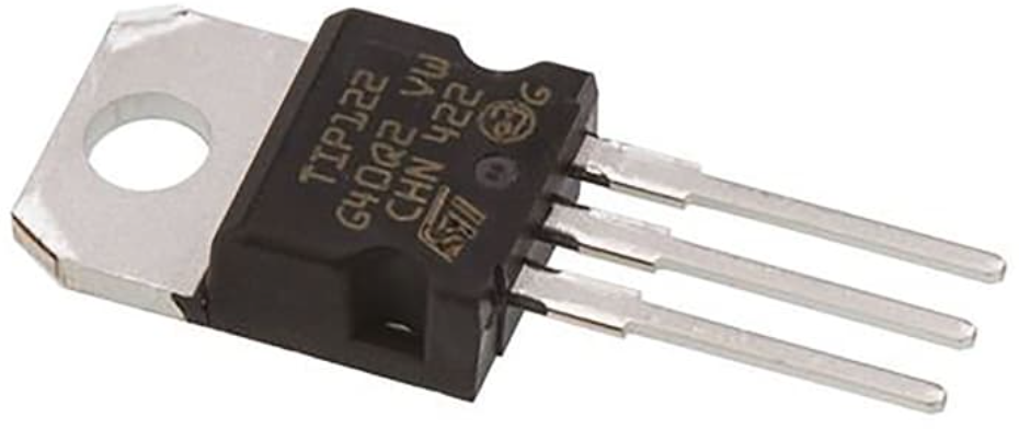
TIP122 NPN transistor 5A 100V
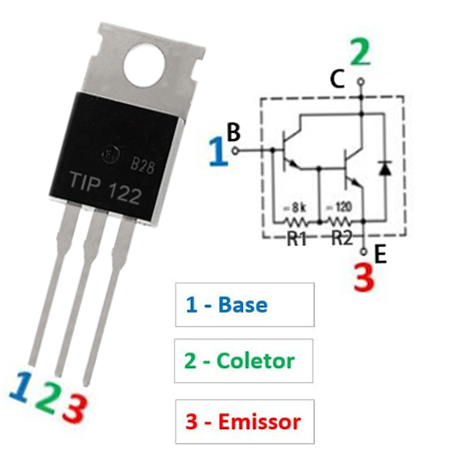
TIP122 Pinout

The TIP122 is a Darlington NPN power transistor housed in a TO-220 package. It features an internal pair of transistors with resistors and a base-emitter protection diode, making it ideal for high-gain switching and amplification. Below is the detailed pin configuration:
| Pin Number | Pin Name | Description |
|---|---|---|
| 1 | Base (B) | Input pin that controls the transistor; requires small current to turn on |
| 2 | Collector (C) | Main current-carrying terminal; connected to load |
| 3 | Emitter (E) | Current flows out from this terminal; typically connected to ground |
The TIP122 integrates internal resistors (R1 = 7kΩ and R2 = 70Ω) and a diode for safe and efficient Darlington operation. It is commonly used in motor drivers, relay drivers, and power control circuits due to its high gain and ease of use.
TIP122 Equivalent
This table is a replacement table for the equivalent type TIP122. They are both NPN type transistors, and their main role in circuits is power amplification, circuit switching, and so on.
| Picture | Name | Makers | Maximum Power (W) | Maximum Current (A) | Maximum Voltage (V) | Package Type |
|---|---|---|---|---|---|---|
 |
TIP122 | STMicroelectronics | 65 | 5 | 100 | TO-220 |
 |
MJ11015 | Motorola | 120 | 15 | 80 | TO-3 |
 |
2N3055 | Motorola | 115 | 6 | 40 | TO-3 |
 |
2N4922G | ON Semiconductor | 30 | 3 | 60 | TO-220 |
 |
MJE3055TG | ON Semiconductor | 75 | 10 | 60 | TO-220 |
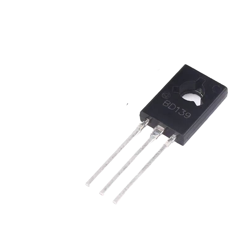 |
BD139 | STMicroelectronics | 35 | 1.5 | 80 | TO-126 |
Note:
The best substitute in this table is MJE3055TG, its parameters are similar to TIP122, when replacing TIP122, just make sure that the actual circuit voltage does not exceed 60 V. When using BD139 as a substitute, there are many more constraints, you need to pay attention to the actual circuit power, current, and voltage do not exceed 35W, 1.5A, and 80 V. When using the other models in the table as a substitute, you also need to pay attention to the actual conditions in the circuit. When using the other models in the table as alternatives, it is also necessary to pay attention to the actual conditions in the circuit.
TIP122 Circuit Diagram
TIP122 Transistor Pinout
TIP122 Specific Parameters:
Package type: TO-220;.
Transistor type: NPN type Darlington transistor;
Maximum DC gain: 1000 (theoretically can amplify current up to 1000 times);
Continuous collector current is: 5A;
Maximum collector-emitter withstand voltage value: 60V;.
Maximum collector base voltage: 60V.
Peak load current: 8A (not sustainable, longer duration will burn out the components);
Operating temperature: -65 to +150 ℃ (the design of the circuit should be careful to avoid prolonged exposure to extremely low or high temperatures)
Principle of operation and internal structure:
As shown in the right half of the tip122 Picture, tip122 consists of two NPN transistors connected to each other (the emitter of the first transistor is connected to the base of the second transistor), so that the amplification of the current can be realised, if the first transistor amplification is A, the second amplification is B then the amplification power of the Darlington tube is A*B.

Tip122 enlarged experimental diagram
From the figure, we can see that the input current is 42.2ma, the output current is 3.09A, and the amplification is 3.09/0.0422=73.2 times. Why not to the actual 1000 times? Because the energy in the circuit can not be generated out of thin air, so there needs to be a power supply, theoretically speaking, as long as the power supply is large enough then the current gain can reach 1000.
More Like This

MMBT5550LT1G
onsemi

MMBT2222A
HY Electronic (Cayman) Limited
MMBT3904
HY Electronic (Cayman) Limited
MMBT2907A
HY Electronic (Cayman) Limited

TIP41C
Fairchild Semiconductor

PMBT3904,215
NXP Semiconductors

TIP120
Central Semiconductor Corp

TIP36C
Central Semiconductor Corp
TIP35C
Central Semiconductor Corp

TIP3055
Central Semiconductor Corp
TIP2955
Central Semiconductor Corp
TIP147
Central Semiconductor Corp
Also Add to Cart

2STF1360
STMicroelectronics

TIP35C
onsemi

MMBTA92
onsemi

BCP53-16
Diotec Semiconductor

MJD44H11-1G
onsemi

MMBT3906TT1G
onsemi

BD140
onsemi

NSS60600MZ4T1G
onsemi

UMT2222AT106
Rohm Semiconductor

2SAR573D3FRATL
Rohm Semiconductor
2SCR574D3FRATL
Rohm Semiconductor
BCP55-16
Diotec Semiconductor
Related Products
MMBT5550LT1G
onsemi
MMBT2222A
HY Electronic (Cayman) Limited
MMBT3904
HY Electronic (Cayman) Limited
MMBT2907A
HY Electronic (Cayman) Limited
TIP41C
Fairchild Semiconductor
PMBT3904,215
NXP Semiconductors
TIP120
Central Semiconductor Corp
TIP36C
Central Semiconductor Corp
TIP35C
Central Semiconductor Corp
TIP3055
Central Semiconductor Corp
TIP2955
Central Semiconductor Corp
TIP147
Central Semiconductor Corp
TIP142
Central Semiconductor Corp

2N2369AUB
Microchip Technology
BCX17
onsemi

BCP69
onsemi
BCP53
onsemi
PZT2907A
onsemi

2SC5200
STMicroelectronics

2N2907A
Micro Commercial Co
BCP52-16
STMicroelectronics

MMBTA92
STMicroelectronics

2N3773
STMicroelectronics
,TO-226_straightlead.jpg "2N5551")
2N5551
onsemi
MPSA92
onsemi
MPS751G
onsemi

MJD44H11
onsemi
MJD127
onsemi
2SC4617
onsemi
TIP42C
onsemi
Please send RFQ , we will respond immediately.
