
TDA7297 Amplifier & Circuit Diagram | vs TPA3116
- Output Type: 2-Channel (Stereo)
- Max Output Power x Channels@Load: 15W x 2 @ 8Ohm
- Voltage-Supply: 6.5V ~ 18V
- Package: 15-Multiwatt


FREE delivery for orders over HK$250.00

Quick response, quick quotaton

Flash shipment,no worries after sales

Original channel,guarantee of the authentic products
TDA7297
tda7297
If you’re working on a small audio project or building your own speaker system, the TDA7297 amplifier chip is something you’ll find really handy. It’s a stereo amplifier from STMicroelectronics that’s widely used in things like desktop speakers, small sound systems, TVs, and even car audio setups.
What’s great about this chip is that it gives you two separate audio channels, perfect for stereo sound. With just a simple 12V power supply, each channel can push out up to 15 watts, giving you plenty of volume for smaller setups. It also accepts a wide power range, anywhere from 6V to 18V, making your design flexible.
One feature you’ll appreciate is the built-in mute function, which cuts out annoying popping sounds when turning your system on or off. Plus, it protects itself with built-in safeguards against overheating and accidental short circuits.
Overall, it’s ideal for DIY audio projects, compact speakers, and upgrading your TV or car audio.
tda7297 pinout diagram
| Pin Number | Pin Name | Description |
|---|---|---|
| 1 | OUT1 | Output channel 1 (Speaker Output) |
| 2 | OUT1 | Output channel 1 (Speaker Output) |
| 3 | GND | Ground |
| 4 | VCC | Positive Power Input (6~18V, Recommended 12V) |
| 5 | OUT2 | Output channel 2 (Speaker Output) |
| 6 | OUT2 | Output channel 2 (Speaker Output) |
| 7 | GND | Ground |
| 8 | SVR | Ripple Suppression Control (Connect Ripple Capacitor) |
| 9 | IN2 | Input Channel 2 (Audio Signal Input) |
| 10 | N.C | No Connection |
| 11 | N.C | No Connection |
| 12 | IN1 | Input Channel 1 (Audio Signal Input) |
| 13 | MUTE/ST-BY | Mute and Standby Control (Active High) |
| 14 | GND | Ground |
| 15 | VCC | Positive Power Input (6~18V, Recommended 12V) |
When you’re using the TDA7297 amplifier chip, here’s what you should keep in mind to get the best results:
First, your power supply should ideally be around 12 volts, although anything from 6V to 18V will work. To keep your audio clean and stable, it’s good practice to add a large filtering capacitor (like 2200µF/25V) right at the power input.
For connecting your speakers, use the OUT1 and OUT2 pins. Choose speakers with 4Ω to 8Ω impedance and double-check your polarity—hooking it up backward can mess things up.
At the input side (IN1 and IN2 pins), make sure you add coupling capacitors (around 1µF to 10µF). These capacitors help block unwanted DC signals and improve your audio quality.
There’s also an SVR pin, which you’ll want to connect to ground through a capacitor (10µF to 47µF). This helps reduce background noise and enhances your sound clarity.
If you don’t need the mute feature, you can safely ground or leave the MUTE pin disconnected. Also, don’t forget—proper grounding is crucial. Connect all the ground pins clearly to a common ground line.
Finally, the TDA7297 can get pretty warm during use, so always pair it with a suitable heat sink to prevent overheating and ensure stable performance.
tda7297 equivalent amplifier ic

| Parameter / Model | TDA7297 | TDA7266 | TDA7266SA | TDA7292 | TDA2009A |
|---|---|---|---|---|---|
| Number of Channels | Stereo | Stereo | Stereo | Stereo | Stereo |
| Typical Output Power | 2×15W (12V, 8Ω) | 2×7W (11V, 8Ω) | 2×7W (11V, 8Ω) | 2×20W (28V, 8Ω) | 2×10W (24V, 4Ω) |
| Operating Voltage | 6V~18V | 3.5V~18V | 3.5V~18V | ±10V to ±33V | 8V~28V |
| Typical THD | 0.1% | 0.05% | 0.05% | 0.1% | 0.2% |
| Mute Function | Supported | Supported | Supported | Supported | Not Supported |
| Thermal Protection | Supported | Supported | Supported | Supported | Supported |
| Short Circuit Protection | Supported | Supported | Supported | Supported | Supported |
| Package Type | Multiwatt-15 | Multiwatt-15 | Multiwatt-15 | Multiwatt-11 | Multiwatt-11 |
When you’re looking to swap out your TDA7297 amplifier chip, there are a few things you’ll want to keep in mind to avoid issues down the line.
First off, always match the power output of your new chip with your project’s needs. If your application demands higher power, something like the TDA7292 might be a good choice, but remember—it usually needs a dual power supply or higher voltage. For lower power requirements, chips like TDA7266 or TDA7266SA would suit you better.
Next, double-check your supply voltage. Picking a chip with a compatible voltage range is key to preventing accidental damage.
Also, even though these chips generally come in similar Multiwatt packages, their pin layouts might vary slightly. Always verify pin compatibility and adjust your circuit accordingly.
Finally, consider if features like mute functionality or built-in thermal and short-circuit protection matter for your setup. Chips like the TDA7266SA and TDA7292 have these handy features, improving your amplifier’s reliability and peace of mind.
tda7297 amplifier circuit schematic

Let me walk you through a typical TDA7297 audio amplifier circuit so you can easily set up your own system.
First, the power supply: use around 6-18 volts (12V is ideal). Add both a large electrolytic capacitor (around 470µF) and a smaller ceramic capacitor (100nF) near the power pin to clean up noise and keep things stable.
For your audio inputs (IN1 and IN2), place 0.22µF coupling capacitors. These block unwanted DC, keeping your sound clear and protecting the chip.
There’s also a handy mute and standby circuit. Using a simple resistor-capacitor network here helps eliminate those annoying popping noises when turning the amp on or off.
The chip outputs in a bridge configuration, directly driving two speakers (ideally 4Ω–8Ω). Be careful to match speaker impedance properly for best performance.
Lastly, grounding matters—combine signal and power grounds effectively on your PCB layout to cut down noise. And remember, this chip can run hot, so add a decent heatsink to keep it cool and reliable.
tda7297 audio amplifier wiring
| Pin Number | Pin Name | Description and Notes |
|---|---|---|
| 1 | OUT1+ | Left channel speaker positive terminal |
| 2 | VCC | Power supply positive, recommended 6~18V DC |
| 3 | OUT2+ | Right channel speaker positive terminal |
| 4 | GND | Power negative, common ground |
| 5 | IN2 | Right channel audio input (via 0.22µF coupling capacitor) |
| 6 | IN1 | Left channel audio input (via 0.22µF coupling capacitor) |
| 7 | MUTE | Mute control (connected via RC circuit, optional) |
| 8 | ST-BY | Standby control (connected via RC circuit, optional) |
| 9 | OUT2- | Right channel speaker negative terminal |
| 10 | OUT1- | Left channel speaker negative terminal |
Let me give you some quick tips on wiring your TDA7297 amplifier to make sure everything runs smoothly.
First, use a stable DC power supply between 6V and 18V—12 volts works best. Be sure to add a 470µF capacitor along with a small 100nF capacitor near the power pins to filter out any noise.
When hooking up your speakers, pick ones rated at 4 to 8 ohms. Remember, the output uses a bridged connection, so don’t ground the speakers or accidentally short the outputs—that could fry your chip.
On the audio input side, add a small 0.22µF coupling capacitor to block DC voltages and keep the chip safe. Also, keep your input signals between 100mV to 500mV RMS for the best sound quality.
If you want to avoid annoying pops when powering on, use a simple RC network (a 10kΩ resistor and 10µF capacitor) on the mute and standby pins. If you don’t need that feature, just tie those pins directly to your VCC line.
Lastly, don’t forget proper cooling—the TDA7297 can get hot, so attach a suitable heatsink to ensure reliable performance.
tda7297 stereo amplifier project
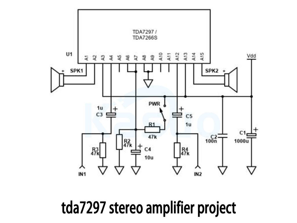
Let’s walk through building your TDA7297 stereo amplifier step by step.
Power Supply: Start by connecting a 6V to 18V DC power source (12V is ideal). Make sure the polarity is correct—incorrect connections can damage the chip. It’s a good idea to use a fuse for extra protection.
Audio Input: For the left and right channels, connect your audio source (like a phone or computer) through 1µF capacitors to the IN1 and IN2 pins on the chip. These capacitors help block DC and pass only the audio signal.
Mute/Standby: When powering up, first switch the mute pin to silence to prevent any popping sounds. After the power stabilizes, you can switch it to active mode.
Speakers: Connect your left and right speakers to the respective output pins (SPK1 and SPK2). Ensure the speaker impedance is between 4Ω and 8Ω for optimal performance.
Cooling: TDA7297 can get hot, so don’t forget to attach a large heatsink to keep things cool.
Also, keep signal wires away from high-current paths to avoid noise and interference. If you need extra protection, consider adding resistors or fuses to the outputs.
tda7297 subwoofer amplifier circuit
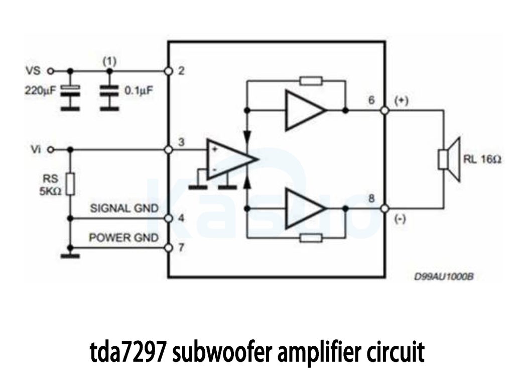
This circuit diagram shows a bridged amplifier (BTL) setup, where two power amplifiers each handle a part of the audio signal, effectively driving a 16Ω speaker. The bridged configuration helps boost output power, which is perfect for driving subwoofers that require higher power, especially in the lower frequency range.
The power supply is filtered with capacitors (220µF and 0.1µF) to ensure stable voltage. The audio input signal is passed through a 5kΩ resistor to prevent any excess signal from damaging the amplifier.
By separating the signal ground (SIGNAL GND) and power ground (POWER GND), the circuit minimizes noise interference, improving sound quality.
The output is connected to a 16Ω speaker, commonly used in subwoofers, allowing it to handle higher power. This setup is very similar to the TDA7297 amplifier, which also uses a bridged output and is ideal for applications requiring powerful bass output.
In summary, this design is perfect for subwoofer applications, providing the necessary power and efficiency for driving low-frequency sound.
tda7297 class ab amplifier circuit
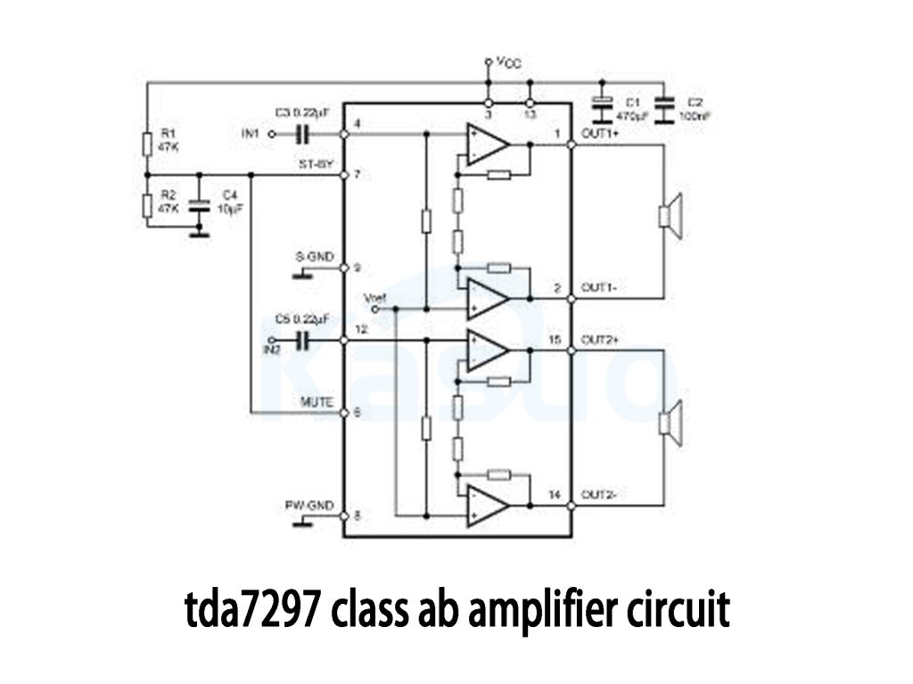
The TDA7297 is a dual-channel bridge power amplifier (BTL) that combines the benefits of both bridge amplification (BTL) and Class AB amplification. Even though it uses a bridged output mode, its operation is similar to that of a Class AB amplifier, which is why it’s often categorized as a Class AB amplifier.
In the BTL mode, the TDA7297 uses two independent output channels connected in a bridge configuration. This setup effectively doubles the output power compared to a single-channel amplifier, which is great for driving speakers with higher power demands.
Class AB amplifiers work by balancing efficiency and distortion. They operate partially in Class A mode (for low distortion) and partially in Class B mode (for higher efficiency). TDA7297 follows this design philosophy, offering both high efficiency and low distortion, making it perfect for high-fidelity audio applications.
So, while TDA7297 is a bridged amplifier, it still provides the benefits of a Class AB design, making it ideal for clear, powerful sound with reduced distortion.
More Like This

74HCT280D,653
NXP USA Inc.

74HCT280N,652
NXP USA Inc.
N74F280BN,602
NXP USA Inc.

1621B2UZZGR
Texas Instruments
1621B1UZZGR
Texas Instruments

SN74S280NSRG4
Texas Instruments

SN74LS280DRG4
Texas Instruments
SN74AS286NSRG4
Texas Instruments
SN74AS286DRG4
Texas Instruments
SN74AS280DRG4
Texas Instruments
SN74ALS280DRG4
Texas Instruments
SN74ALS280DG4
Texas Instruments
Also Add to Cart

DP83640TVVX/NOPB
Texas Instruments

W681512SG
Nuvoton Technology Corporation
AD8628AUJZ
Analog Devices

SI2434-C-FS
Skyworks Solutions Inc.

LD39200PUR
STMicroelectronics

AD7677ASTZ
Analog Devices Inc.

CXDQ3A8AM-WG
CXMT

LT1129IST-3.3
Analog Devices

PIC16LF876-04I/SO
Microchip Technology

EP1K100QI208-2
Intel

CAT809ZTBI-GT3
onsemi
ADM213EARSZ
Analog Devices Inc.
Related Products
74HCT280D,653
NXP USA Inc.
74HCT280N,652
NXP USA Inc.
N74F280BN,602
NXP USA Inc.
1621B2UZZGR
Texas Instruments
1621B1UZZGR
Texas Instruments
SN74S280NSRG4
Texas Instruments
SN74LS280DRG4
Texas Instruments
SN74AS286NSRG4
Texas Instruments
SN74AS286DRG4
Texas Instruments
SN74AS280DRG4
Texas Instruments
SN74ALS280DRG4
Texas Instruments
SN74ALS280DG4
Texas Instruments

CY74FCT480BTSOCTG4
Texas Instruments
CD74AC280M96G4
Texas Instruments
74ACT11286NG4
Texas Instruments
74ACT11286N
Texas Instruments

SY10E193JZ TR
Microchip Technology
SY10E193JZ
Microchip Technology
SY10E160JZ TR
Microchip Technology
SY10E160JZ
Microchip Technology
SY100S360JZ-TR
Microchip Technology
SY100S360JZ
Microchip Technology
SY100E193JZ TR
Microchip Technology
SY100E193JZ
Microchip Technology
SY100E160JZ TR
Microchip Technology
SY100E160JZ
Microchip Technology
SN74S280NSRE4
Texas Instruments
SN74S280NSR
Texas Instruments
SN74LS280DRE4
Texas Instruments
SN74LS280DR
Texas Instruments
Please send RFQ , we will respond immediately.
