
SN74HC08N datasheet | pinout & pdf
- Logic Type: AND Gate
- Number of Circuits: 4
- Number of Inputs: 2
- Package: 14-PDIP


FREE delivery for orders over HK$250.00

Quick response, quick quotaton

Flash shipment,no worries after sales

Original channel,guarantee of the authentic products
SN74HC08N Quad 2 input AND gate integrated circuit IC demonstration
sn74hc08n
If you’re looking into using the SN74HC08N chip, here’s what makes it a great pick for your projects. It’s got four independent 2-input AND gates, each capable of handling logic signals separately. The chip works smoothly with supply voltages anywhere between 2V and 6V, which gives you a lot of flexibility.
Thanks to its high-speed CMOS design, it switches fast but uses very little power—typically around 1µA, perfect for battery-powered gadgets or low-energy projects. Another handy feature is its standard TTL-compatible inputs, which make it simple to integrate with your existing circuits.
It comes in a user-friendly DIP-14 package, making soldering, installation, and troubleshooting straightforward, especially in educational settings or labs. Plus, it can drive small LEDs directly without extra parts.
You’ll often see this chip used in digital circuits, logic controllers, teaching experiments, signal processing, and interfacing tasks. Reliable, energy-efficient, and easy to use, it fits perfectly into industrial electronics, consumer gadgets, or your next DIY electronics project.
sn74hc08n pinout logic gate

| Pin Number | Pin Name | Function Description |
|---|---|---|
| 1 | 1A | First AND gate input A |
| 2 | 1B | First AND gate input B |
| 3 | 1Y | First AND gate output Y (Y = A·B) |
| 4 | 2A | Second AND gate input A |
| 5 | 2B | Second AND gate input B |
| 6 | 2Y | Second AND gate output Y (Y = A·B) |
| 7 | GND | Ground (0V) |
| 8 | 3Y | Third AND gate output Y (Y = A·B) |
| 9 | 3A | Third AND gate input A |
| 10 | 3B | Third AND gate input B |
| 11 | 4Y | Fourth AND gate output Y (Y = A·B) |
| 12 | 4A | Fourth AND gate input A |
| 13 | 4B | Fourth AND gate input B |
| 14 | VCC | Positive power supply input (2V to 6V) |
When you’re setting up the SN74HC08N chip, there are a few simple things you need to keep in mind. First, make sure pin 7 (GND) is properly grounded, and pin 14 (VCC) is connected to your positive supply voltage, usually around 5 volts. Stay within the recommended range (2 to 6 volts) to avoid damaging the chip.
Your input signals should always match standard TTL or CMOS levels—don’t leave inputs floating or feed them higher voltages, as this could cause erratic behavior. Keep in mind, the output pins typically handle up to about 20mA, so don’t overload them; check your external components carefully.
Also, if you’re not using all of the chip’s inputs, tie those unused pins either to ground or to your supply voltage to prevent unnecessary power drain or interference.
By following these guidelines, you’ll keep your SN74HC08N running smoothly in logic experiments, digital signal processing, or interface control projects.
sn74hc08n equivalent gate ic
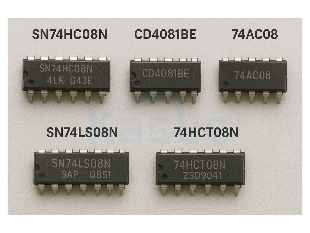
| Parameter/Model | SN74HC08N | CD4081BE | SN74LS08N | 74AC08 | 74HCT08N |
|---|---|---|---|---|---|
| Logic Function | Quad 2-input AND gate | Quad 2-input AND gate | Quad 2-input AND gate | Quad 2-input AND gate | Quad 2-input AND gate |
| Operating Voltage Range | 2V ~ 6V | 3V ~ 15V | 4.75V ~ 5.25V | 2V ~ 6V | 4.5V ~ 5.5V |
| Technology Type | CMOS | CMOS | TTL | CMOS (High-speed) | CMOS Compatible TTL |
| Propagation Delay | ~10 ns | ~100 ns | ~15 ns | ~5 ns | ~15 ns |
| Power Consumption | Ultra-low | Low | Moderate | Very Low | Moderate |
| Input Compatibility | CMOS/TTL | CMOS | TTL | CMOS/TTL | TTL |
| Output Drive Capability | Medium (~20mA) | Weak (~6mA) | Medium (~8mA) | Strong (~24mA) | Medium (~20mA) |
| Package Type | DIP-14 | DIP-14 | DIP-14 | DIP-14 | DIP-14 |
When you’re thinking about replacing the SN74HC08N chip, there are a few key points you should keep in mind. First, always match the voltage requirements of your circuit. For example, the CD4081BE handles higher voltages—up to 15 volts—which makes it great if your circuit runs above 5 volts. On the other hand, the SN74LS08N strictly needs a steady 5-volt supply.
Also, consider your input signals. Chips like the SN74HCT08N and SN74LS08N play nicely with standard TTL signals, so they’re ideal if you’re mixing with older TTL components. The CD4081BE, however, is purely CMOS and won’t be compatible with standard TTL levels.
For speed-sensitive applications, pick something like the 74AC08—it’s super fast. If you’re looking for lower power consumption without sacrificing compatibility, then SN74HC08N or 74HCT08N are your best bets.
Lastly, if you need strong output driving capability, again, the 74AC08 wins. Just make sure your replacement fits your voltage, input type, speed, and output needs perfectly, and your circuit will run smoothly.
sn74hc08n and gate circuit example

If you’re experimenting with the SN74HC08N chip, this basic AND gate circuit is a great way to understand how it works. The SN74HC08N is a simple logic gate—it gives a high output only when both inputs are high.
In this setup, your two inputs (pins 1 and 2) connect to DIP switches, which provide a stable high or low signal. When the switches are open, the 10kΩ resistors pull the inputs to ground, ensuring the inputs don’t float around causing unpredictable results. When you flip both switches on, the inputs go high, and the chip outputs a high signal, lighting up the LED through a resistor (R3). If either switch stays off, the LED remains off.
Just make sure your power supply stays between 2V and 6V to protect the chip. Also, pick a suitable resistor (typically between 220Ω to 1kΩ) for the LED to keep the current safe. It’s an easy, practical circuit to show how logic gates behave—perfect for educational purposes or your next DIY project.
sn74hc08n digital logic wiring diagram
If you’re wiring up the SN74HC08N chip in your next digital logic project, here’s a quick, easy way to get started. First, power it by connecting pin 14 to +5 volts and pin 7 straight to ground. Suppose you’re using the first AND gate in this chip: hook your two input signals up to pins 1 and 2, and your output will be pin 3. You can connect this output to an LED (don’t forget to use a resistor!) or another logic circuit.
Always make sure you tie any unused input pins to either ground or +5 volts—don’t leave them floating around, as this can cause unpredictable behavior. Adding a 0.1µF capacitor near the power pins helps smooth out noise, keeping things running reliably. And keep your loads manageable—each output pin can drive around 20mA, so for heavier tasks, consider adding extra components. Follow these tips, and your logic circuits will run smoothly and reliably.
sn74hc08n arduino interface project
Here’s a simple project where you use the SN74HC08N AND gate chip to control an LED with an Arduino. First, you’ll need a few basic components: the SN74HC08N chip, an Arduino Uno, an LED, a current-limiting resistor (220Ω or 330Ω), a couple of DIP switches, jumper wires, and a breadboard.
Start by connecting the Arduino’s 5V to the VCC pin of the SN74HC08N and the ground pin (GND) to the chip’s GND. For the inputs, wire the DIP switches to the chip’s input pins (1A, 1B) and make sure to add pull-down resistors to keep the inputs stable. The output from the chip will go to the LED, with a current-limiting resistor to protect the LED.
Upload the code to your Arduino, and test by flipping the DIP switches. The LED will only light up when both switches are set to HIGH—demonstrating how the AND gate works. This simple setup is a great way to get familiar with using logic gates in Arduino projects.
sn74hc08n logic ic applications
The SN74HC08N AND gate is a highly versatile digital logic IC that finds its place in various applications. It’s widely used in basic logic operations, performing the essential AND function in digital circuits, which is key for tasks like signal processing and decision-making. This chip is often integrated into more complex control circuits, where it works alongside other logic gates to ensure systems only activate when certain conditions are met, like turning on a device when multiple inputs are true. It also plays an important role in timing circuits, controlling signals in digital clocks, timers, and other time-based applications. In sensor-driven systems, it ensures that actions, like triggering alarms, only happen when all conditions are satisfied. Whether it’s for managing control signals in embedded systems, verifying data integrity in communications, or protecting devices with security circuits, the SN74HC08N is crucial for reliable and efficient digital operations. It even helps manage power by controlling when devices are powered on, especially in battery-operated devices.
More Like This

PCK9456BD,157
NXP USA Inc.
PCK9448BD,151
NXP USA Inc.
PCK9448BD,128
NXP USA Inc.
PCK9447BD,151
NXP USA Inc.
PCK9447BD,128
NXP USA Inc.
PCK9446BD,128
NXP USA Inc.
PCK9446BD,157
NXP USA Inc.
PCK942PBD,151
NXP USA Inc.
PCK942PBD,128
NXP USA Inc.
PCK942CBD,151
NXP USA Inc.
PCK942CBD,128
NXP USA Inc.

PCK3807APW,118
NXP USA Inc.
Also Add to Cart

ADS7029QDCURQ1
Texas Instruments

78M6610+PSU/C09
Analog Devices Inc./Maxim Integrated

HMC1000LP5E
Analog Devices Inc.

AD8044AR-14
Analog Devices Inc.

ISD5116SYI
Nuvoton Technology Corporation

SY88933VKI
Microchip Technology

LTC3454EDD
Analog Devices

LTC1064-4MJ
Analog Devices Inc.

CD4504BM96
Texas Instruments

MD8243/B
Rochester Electronics, LLC

LM2596T-5.0
National Semiconductor

UCC2973PW
Texas Instruments
Related Products
PCK9456BD,157
NXP USA Inc.
PCK9448BD,151
NXP USA Inc.
PCK9448BD,128
NXP USA Inc.
PCK9447BD,151
NXP USA Inc.
PCK9447BD,128
NXP USA Inc.
PCK9446BD,128
NXP USA Inc.
PCK9446BD,157
NXP USA Inc.
PCK942PBD,151
NXP USA Inc.
PCK942PBD,128
NXP USA Inc.
PCK942CBD,151
NXP USA Inc.
PCK942CBD,128
NXP USA Inc.
PCK3807APW,118
NXP USA Inc.
PCK3807APW,112
NXP USA Inc.

PCK3807AD,118
NXP USA Inc.

PCK3807ADS,118
NXP USA Inc.
PCK3807ADS,112
NXP USA Inc.

PCK3807ADB,118
NXP USA Inc.
PCK3807ADB,112
NXP USA Inc.
PCK3807AD,112
NXP USA Inc.

PCK351D,118
NXP USA Inc.

PCK351DB,118
NXP USA Inc.
PCK351DB,112
NXP USA Inc.
PCK351D,112
NXP USA Inc.
PCK2111BD,118
NXP USA Inc.
PCK2111BD,151
NXP USA Inc.
PCK2111BD,157
NXP USA Inc.
PCK210BD,118
NXP USA Inc.
PCK210BD,151
NXP USA Inc.
PCK210BD,157
NXP USA Inc.

PCK2002PLPW,118
NXP USA Inc.
Please send RFQ , we will respond immediately.
