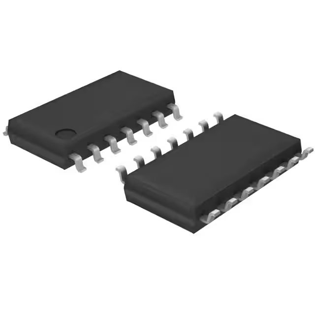
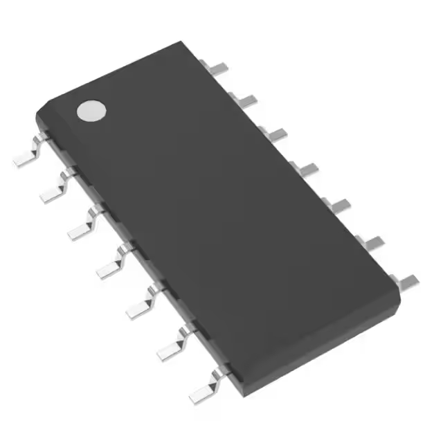
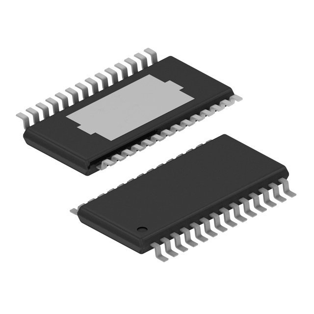
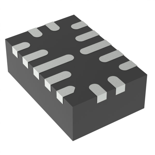
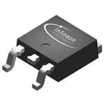
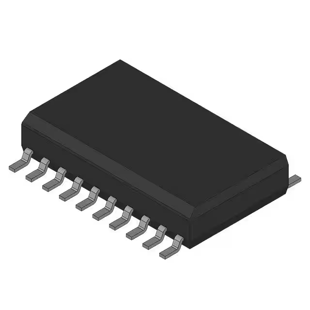
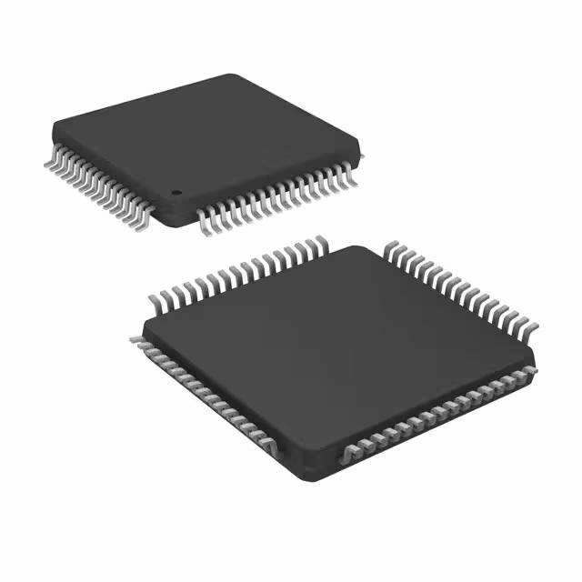
SI3402-B-GM QFN 20_5x5mm datasheet
- Type: Controller (PD), DC/DC
- Channels: 1
- Power Max: 17 W
- Package: 20-VQFN Exposed Pad

FREE delivery for orders over HK$250.00

Quick response, quick quotaton

Flash shipment,no worries after sales

Original channel,guarantee of the authentic products
Si3402B evaluation board controller design guide
Detailed Functional Explanation of Si3402B Circuit:

| Circuit Section | Component | Detailed Functional Description |
|---|---|---|
| RJ-45 Input Interface (J1) | RJ-45 Jack Internal Rectifier Bridge ESD Protection Capacitors |
Receives IEEE 802.3af-compliant PoE voltage (typically 48V, range 44-57V DC) via Ethernet cable. The integrated diode bridge (D11-D18) rectifies input voltage, and ESD protection capacitors (C10~C17) protect the circuit from electrostatic discharge events. |
| Si3402B Chip (U1) | Integrated PD Interface PWM Controller MOSFET Switch |
Performs automatic IEEE 802.3af PoE detection, classification, and power control. Internal PWM controller drives MOSFET switching, allowing power conversion through the flyback transformer. Reduces external component count, increases efficiency, and lowers cost. |
| Flyback Transformer (T1) | Isolated Transformer | Provides galvanic isolation between input (high voltage) and output (low voltage) sides, enhancing safety. Converts high-voltage PoE input into a low-voltage AC signal suitable for rectification and filtering on the secondary side. |
| Output Rectification and Filtering | Schottky Diode (D3) Filter Inductor (L1=1µH) Filter Capacitors (C5=1000µF, C6=100µF) |
High-frequency AC from the transformer secondary is rectified by the Schottky diode, then smoothed by the inductor and capacitors, providing a stable and clean 5V DC output to the load. |
| Feedback Control Circuit | TL431 Voltage Reference (U3) Optocoupler (U2) Feedback Resistors (R6, R7) |
Accurately senses output voltage variations through TL431 and generates an error signal. This signal is sent through an optocoupler (providing isolation) back to Si3402B’s feedback pin, dynamically adjusting PWM duty cycles to maintain precise 5V output. |
| Protection and Auxiliary Circuitry | Overvoltage, Overtemperature, Current Limit Protection Classification Detection Resistors (R1, R2) |
Built-in overvoltage (OVP), undervoltage lockout (UVLO), thermal shutdown (OTP), and current limit protection to safeguard the circuit. Classification resistors communicate the PD’s power requirements to the PoE source equipment (PSE). |
Detailed Specification Highlights of Si3402B Chip:

si3402-b-gm qfn 20_5x5mm reference design
| Parameter | Specific Description and Values |
|---|---|
| Input Voltage Range | 44~57V DC (compliant with IEEE802.3af PoE standard) |
| Output Voltage Capability | Commonly configured for 5V; also supports 3.3V, 9V, 12V outputs based on external configuration |
| Maximum Output Power | Up to 13W (IEEE 802.3af Class 3) |
| Integration Level | Integrated PoE detection interface, PWM controller, MOSFET power switch, and diode bridge for simplified external circuitry |
| Protection Functions | Integrated overvoltage (OVP), overcurrent (OCP), undervoltage lockout (UVLO), and thermal shutdown (OTP) protection |
| Package Type | QFN-20 (5mm × 5mm) with exposed thermal pad |
FAQ
1. What is the pin configuration for the Si3402-B-GM (QFN-20) package?
The Si3402-B-GM uses a QFN-20 package (5mm × 5mm), featuring 20 bottom-side pins with a central thermal pad to enhance heat dissipation. Proper PCB layout should include thermal vias and sufficient copper areas for effective cooling.
2. What should I pay attention to when using the Si3402-B evaluation board?
Ensure the input power source complies with IEEE 802.3af standards (such as a compliant PSE switch or mid-span injector).
Connect an appropriate load at the output (e.g., 5V load) to accurately evaluate the board’s performance.
Verify jumper configurations and settings according to your specific evaluation requirements before first-time use.
3. How should I optimize the feedback loop in an Si3402 controller design?
Use a TL431 and optocoupler feedback network for precise and stable voltage regulation.
Place feedback network components close to the Si3402 feedback pins to minimize noise.
Select feedback resistors with tight tolerances (±1%) to ensure accurate output voltage regulation.


