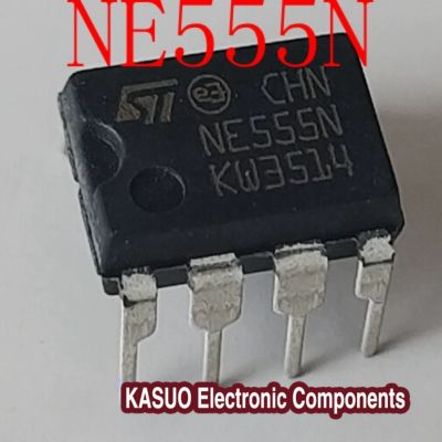
NE555N Timer, Circuits, Pinout, Projects STMicroelectronics
- Brands: STMicroelectronics
- Download: -
- Price: inquiry
- In Stock: 6,935
- Type: 555 Type, Timer/Oscillator (Single)
- Frequency: 500kHz
- Voltage-Supply: 4.5V ~ 16V
- Package: 8-DIP (0.300, 7.62mm)
PAANO MAGTEST NANG NE555N IC’s/ELECTRONICS GUIDE PH
NE555N Circuits
Overview of NE555
NE555 is an integrated chip, the internal structure includes RS trigger, comparator, voltage comparator of the three main circuit modules, the lead out of the external pins are mainly for and other devices connected to each other to form a circuit that can achieve the desired function.NE555 was designed initially to provide a fast and simple to achieve the timer function, but because of the excellent performance and cheap price, was Widely used in various aspects; for example, timing control circuits, clock generator circuits, PWM generation circuits and so on.

ne555n circuits Picture
Next we analyse the internal structure of the NE555n in detail:
Firstly, there are two comparators, the threshold comparator and the trigger comparator, where the threshold comparator is connected to pin 6 (THR) and the trigger comparator is connected to pin 2 (TRIG). The main function of these two comparators is to detect the change of external threshold voltage or trigger voltage (after detecting the change, it is passed to the RS trigger at the back).
Threshold Comparator: When the voltage rises at the THR pin, the comparator will output a high level signal. When the voltage at the THR pin exceeds the voltage at the TRIG pin, the output of the comparator will be inverted.
Trigger Comparator: this comparator will output a low signal when the voltage is falling at the TRIG pin. When the voltage at the TRIG pin falls below the voltage at the THR pin, the output of the comparator will invert.
Next is an RS flip-flop, the main function is to store the state of pin 3. The state of the RS flip-flop is controlled by the two previous comparators; the threshold comparator controls the reset of RS and the trigger comparator controls the set of RS.
Then the next is a voltage comparator for detecting the voltage of the power supply, the output is connected to the RS flip-flop for the purpose that when the power supply is too low, the comparator will output a high level signal for the RS flip-flop to reset, so as to realise the function of power supply detection.
The last one is an output stage directly connected to the RS flip-flop and controls the state of the output pin (pin 3).
More Like This
Also Add to Cart
MC34074P
onsemi
SSM2141SZ
Analog Devices Inc.
LM358A-SR
3PEAK
AD8531ARTZ
UMW
OPA340NA
UMW
AD8541ARTZ
UMW
LTC4286AUK#TRPBF
Analog Devices Inc.
MP5991GLU-Z
Monolithic Power Systems Inc.
S-35390AH-T8T2U
ABLIC Inc.
DS3231
Jameco ValuePro






;-;-21.jpg)

