NE555DR | Difference Between NE555DR and NE555P
- Type: 555 Type, Timer/Oscillator (Single)
- Frequency: 100kHz
- Voltage-Supply: 4.5V ~ 16V
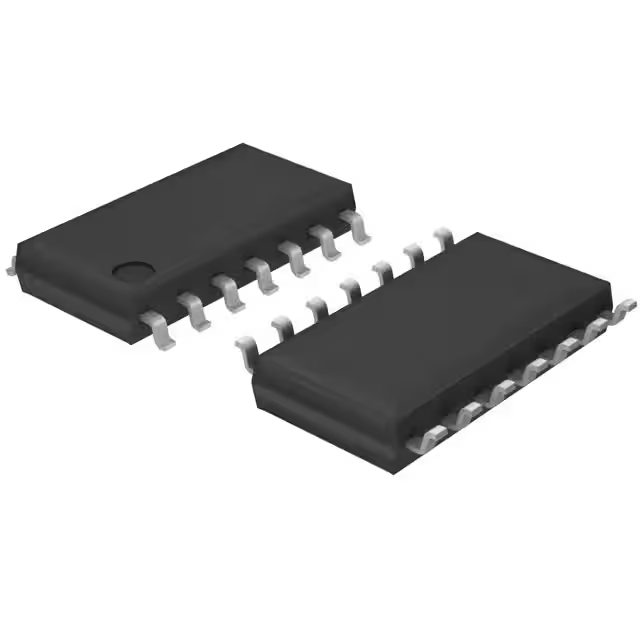
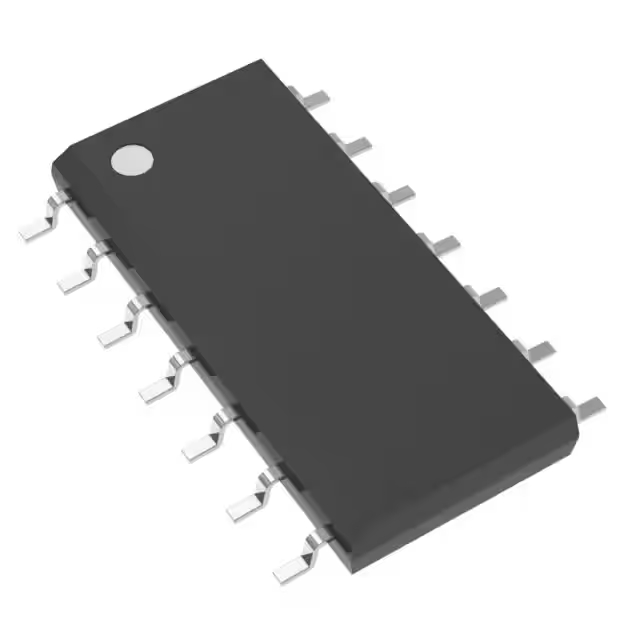
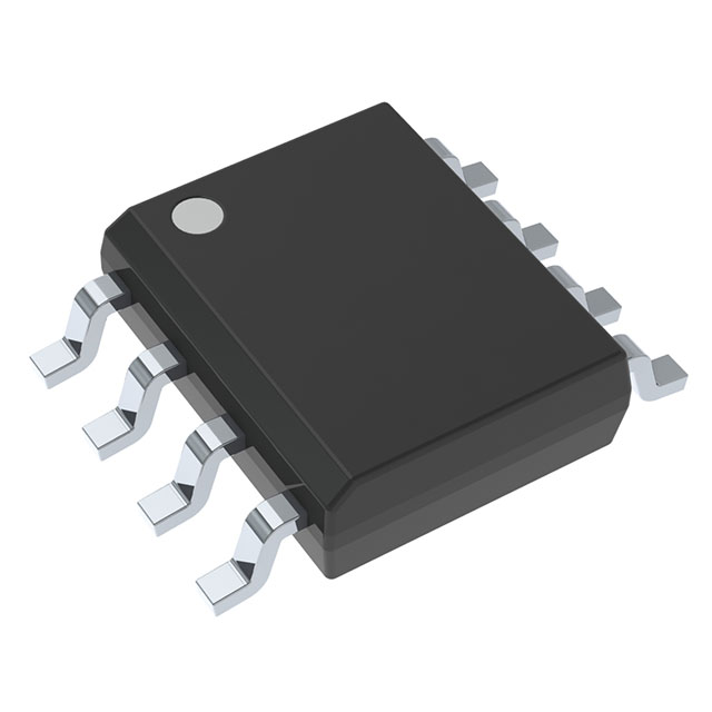
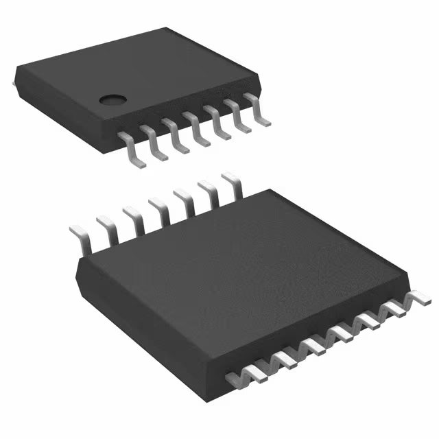
- Package: 8-SOIC (0.154, 3.90mm Width)

FREE delivery for orders over HK$250.00

Quick response, quick quotaton

Flash shipment,no worries after sales

Original channel,guarantee of the authentic products
ne555dr
The NE555DR operates reliably across a wide voltage range—from 4.5V to 16V—which makes power design easier for you. Its timing precision is excellent, whether you’re using it for a one-shot delay or continuous oscillation. You can easily tweak the frequency and duty cycle just by adjusting external resistors and capacitors, offering great flexibility. It provides a solid output current of up to about 200mA, allowing direct driving of LEDs, relays, or even speakers. Its power consumption is quite low, and it works well in industrial environments, from -40°C to 85°C. Plus, it’s packaged in a compact SOIC-8 format, perfect for saving space on your PCB.
ne555dr pinout and functions
| Pin Number | Pin Name | Function Description |
|---|---|---|
| 1 | GND | Ground |
| 2 | TRIG | Trigger input; when voltage is below 1/3 Vcc, the output is set high. |
| 3 | OUT | Output pin; outputs logic level. |
| 4 | RESET | Reset pin; active low, typically connected to Vcc. |
| 5 | CONTROL | Control voltage input; usually connected to a 0.01µF capacitor. |
| 6 | THRESHOLD | Threshold input; when voltage exceeds 2/3 Vcc, output goes low. |
| 7 | DISCHARGE | Discharge pin; connects external timing resistor to capacitor. |
| 8 | Vcc | Power supply pin; operates from 4.5V to 16V. |
When you’re wiring up the NE555DR, some pins need special attention. For example, if you’re not using the RESET pin, just tie it straight to Vcc to avoid accidental resets. The CONTROL pin works best when connected to ground through a small capacitor, usually 0.01μF, to stabilize internal threshold voltages and minimize noise interference. The DISCHARGE pin manages the charging and discharging of your timing capacitor, so picking the right resistor and capacitor here directly affects your frequency and duty cycle accuracy. Finally, ensure your power supply voltage stays stable within the recommended range to keep everything running precisely and smoothly.
ne555dr equivalent timer ic
| Parameter | TLC555CDR | LM555CMX | TS555IDT | ICM7555IBAZ | NA555DR |
|---|---|---|---|---|---|
| Package Type | SOIC-8 | SOIC-8 | SOIC-8 | SOIC-8 | SOIC-8 |
| Operating Voltage (V) | 2 ~ 15 | 4.5 ~ 16 | 2 ~ 16 | 2 ~ 18 | 4.5 ~ 16 |
| Max Output Current (mA) | 100 | 200 | 100 | 100 | 200 |
| Operating Temperature (°C) | -40 ~ 85 | -40 ~ 85 | -40 ~ 125 | -40 ~ 85 | -40 ~ 85 |
| Frequency Range | Up to 2MHz | Up to 500kHz | Up to 2.7MHz | Up to 500kHz | Up to 500kHz |
When you’re choosing replacement chips, first double-check the voltage range to ensure it matches your existing circuit. If your application involves driving heavier loads like relays or LEDs, opt for models like LM555CMX or NA555DR that offer higher output current. Also, consider your operating environment and frequency needs—if your circuit runs in hotter conditions, selecting a wide-temperature-range model like TS555IDT is a smart move. Ultimately, evaluate based on your actual usage scenario to ensure compatibility and stable performance.
ne555dr pwm generator circuit

When you set up a PWM circuit using the NE555 chip, connect pins 2 (Trigger) and 6 (Threshold) together to form a self-oscillating circuit. Adjusting the PWM duty cycle is done with a 10kΩ potentiometer (RV1), two diodes (D1 and D2, both 1N4148), and a 100nF capacitor (C1), as they control the charging and discharging rates, thus determining your PWM frequency and duty cycle.
The PWM output drives an indicator LED (D3) via resistors R2 (1kΩ) and R1 (100Ω). You can also send this PWM signal externally through an OCR interface to control other devices like optocouplers or driver circuits.
It’s great for controlling motor speeds or dimming lights. Be careful not to adjust RV1 fully to either end, as extreme duty cycles can cause instability. Also, ensure your LED resistor suits the 9V supply to protect components from excessive current.
ne555dr monostable circuit schematic

When you’re setting up an NE555DR monostable circuit, the chip acts like a timed switch. When you apply a low-level trigger (below 1/3 of Vcc) to the TRIG pin, the output pin goes high, and capacitor C charges through resistor R_A. Once the voltage on capacitor C reaches 2/3 of Vcc (detected by THRES pin), the output automatically switches back to low, and capacitor C quickly discharges via the DISCH pin.
The pulse duration is controlled by resistor R_A and capacitor C using the formula: t = 1.1 × R_A × C.
Remember, the key pins are TRIG for starting the timing, THRES for ending it, and DISCH for discharging the capacitor. Also, connect the CONT pin to ground via a small capacitor (0.01μF) to avoid noise. If you’re not using the RESET pin, just connect it to Vcc directly to prevent accidental resets.
This setup is perfect for creating accurate delays, pulse shaping, and signal detection circuits.
ne555dr frequency calculation example
When you use an NE555 timer as an astable oscillator, capacitor C repeatedly charges and discharges, determining the output frequency and duty cycle. Specifically, when C charges up, your output goes high. The high-level duration depends on resistors R_A, R_B, and capacitor C:
High-level duration (t_H) ≈ 0.693 × (R_A + R_B) × C
Low-level duration (t_L) ≈ 0.693 × R_B × C
The total oscillation period (T) is simply:
T ≈ 0.693 × (R_A + 2R_B) × C
To get the frequency, you just take the reciprocal:
f ≈ 1.44 / [(R_A + 2R_B) × C]
Duty cycle calculation is also straightforward:
High-level duty cycle ≈ (R_A + R_B) / (R_A + 2R_B)
Knowing these formulas helps you quickly adjust your circuit’s frequency and duty cycle to match your design goals.
ne555dr led flasher circuit design
When you’re building an LED flashing circuit with an NE555, here’s how it’s wired: Connect pin 8 to your 5V or 9V power supply, pin 1 to ground. Pins 2 (Trigger) and 6 (Threshold) are tied together and connected to where resistor R2 meets capacitor C1. Pin 7 (Discharge) goes to the junction between R1 and R2. Pin 4 (Reset) goes directly to your power supply. The output (pin 3) drives your LED through resistor R3, with LED’s other leg grounded. For extra stability, connect pin 5 (Control) to ground through a small 0.01µF capacitor.
Frequency is set by resistors R1, R2, and capacitor C1:
-
High-level duration T_H = 0.693 × (R1+R2) × C1
-
Low-level duration T_L = 0.693 × R2 × C1
-
Total cycle T = T_H + T_L
-
Frequency f = 1.44 / [(R1+2R2) × C1]
For example, with R1=1kΩ, R2=10kΩ, and C1=10μF, the LED flashes at roughly 6.86Hz. To slow it down, just use a bigger capacitor for C1.


