
NCP15XH103F03RC datasheet & price
- ResistanceTolerance: ±1%
- ResistanceinOhms@25°C: 10k
- BValueTolerance: ±1%
- Package: Tape,Reel,Cut Tape


FREE delivery for orders over HK$250.00

Quick response, quick quotaton

Flash shipment,no worries after sales

Original channel,guarantee of the authentic products
NCP15XH103F03RC
When you’re picking a capacitor, this one is a solid choice. It’s a multilayer ceramic capacitor (MLCC) that’s great for decoupling and filtering in your circuits. With a capacitance of 10nF, it’s perfect for high-frequency filtering tasks. The 50V voltage rating ensures it can handle moderate voltage applications without issue. The ±10% tolerance means you’ll have some slight variation, but nothing too drastic. Plus, the X7R dielectric ensures the capacitor stays stable over a wide temperature range from -55°C to 125°C. It’s packaged in the 1206 surface-mount size, which works well for compact designs. You’ll typically find this type of capacitor in power supply filters, RF circuits, and signal processing, helping reduce noise and keep your voltage steady.
NCP15XH103F03RC Equivalent
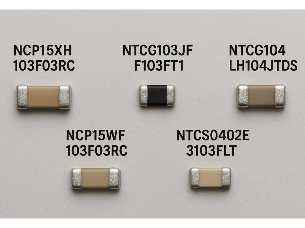
| Parameter | NCP15XH103F03RC | NCP15WF103F03RC | NTCG103JF103FT1 | NTCS0402E3103FLT | NTCG104LH104JTDS |
|---|---|---|---|---|---|
| Package Size | 0402 (1005 Metric) | 0402 (1005 Metric) | 0402 (1005 Metric) | 0402 (1005 Metric) | 0402 (1005 Metric) |
| Nominal Resistance (25°C) | 10kΩ | 10kΩ | 10kΩ | 10kΩ | 100kΩ |
| B Value (25/50°C) | 3380K | 3380K | 3380K | 3380K | 4250K |
| Tolerance | ±1% | ±1% | ±1% | ±1% | ±5% |
| Operating Temperature Range | -40°C ~ 125°C | -40°C ~ 125°C | -40°C ~ 125°C | -40°C ~ 125°C | -40°C ~ 125°C |
| Max Power Dissipation | 63mW | 63mW | 63mW | 63mW | 63mW |
The first few recommended models are very similar to your original NCP15XH103F03RC and will typically work fine as direct replacements. But keep in mind, real-world scenarios might show slight differences—things like thermal response speed or long-term stability. To be safe, I suggest running some tests in your specific application.
However, the TDK NTCG104LH104JTDS is pretty different. Its resistance is 100kΩ with a B-value of 4250K, significantly off from your original choice. This type works best if you’re specifically aiming for a higher resistance sensor or different thermal characteristics. You’d definitely need to revisit and tweak your circuit to ensure it matches your performance goals.
NCP15XH103F03RC Thermistor Circuit Example
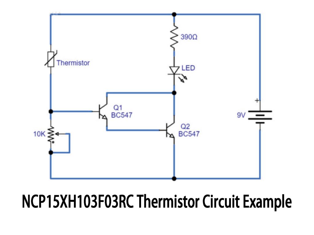
This circuit uses the NCP15XH103F03RC thermistor to detect temperature changes. The thermistor’s resistance decreases as the temperature rises, which is key for triggering the circuit. It’s paired with a 10kΩ resistor to form a voltage divider, and as the temperature shifts, the voltage across the thermistor changes, controlling the transistor Q1.
Q1 (BC547) acts as a switch that, when triggered by the voltage change, allows current to flow to Q2 (BC547). Q2, working as part of a Darlington pair, amplifies the current enough to light up the LED, signaling that the temperature has hit a specific threshold.
Make sure to place the thermistor in the area you want to monitor, and calibrate it so the circuit activates at the right temperature. The 390Ω resistor keeps the LED safe by limiting the current.
NCP15XH103F03RC Temperature Sensor Wiring
To wire the NCP15XH103F03RC thermistor, start by connecting one lead to the Vcc (usually 5V or 3.3V, depending on your microcontroller’s voltage). The other lead goes to an analog input pin on your microcontroller (like A0 on an Arduino), where it will read the voltage across the thermistor.
Next, connect a 10kΩ fixed resistor between the analog input pin and ground (GND). This resistor and the thermistor create a voltage divider. As the temperature changes, the resistance of the thermistor changes, which adjusts the voltage at the junction. The microcontroller reads this voltage and uses it to calculate the temperature.
The power supply comes from the microcontroller, either 5V or 3.3V. The ground from the microcontroller connects to the fixed resistor to complete the circuit. This setup allows the microcontroller to measure temperature by reading the voltage that changes as the thermistor’s resistance varies.
NCP15XH103F03RC in Arduino

To set up the thermistor, place it on the breadboard. One lead connects to 5V (Vcc) from the Arduino, and the other goes to the analog pin A0, where the voltage will be read. You’ll connect a 10kΩ resistor in series with the thermistor, creating a voltage divider. The resistor goes between A0 and ground (GND) on the breadboard.
Use a yellow wire to connect the thermistor to 5V, a red wire to link A0 to the voltage divider, and a black wire for the ground connection. The Arduino gets its power from the USB or external power supply, providing the 5V needed.
The thermistor’s resistance changes with temperature, and this affects the voltage that the Arduino reads at A0. The 10kΩ resistor helps convert these changes into a readable voltage.
NCP15XH103F03RC NTC Curve Characteristics
The NCP15XH103F03RC is a 10kΩ NTC thermistor, meaning its resistance decreases as the temperature rises. This feature is key for temperature sensing applications. At 25°C, the resistance is 10kΩ, and as the temperature goes up, the resistance drops significantly.
For example:
-
At 0°C, it’s around 14kΩ.
-
At 50°C, it’s about 5kΩ.
-
At 100°C, it’s about 1.3kΩ.
This thermistor’s resistance changes are calculated using a formula called the B-parameter equation. The B coefficient is 3950K, which helps determine how resistance changes with temperature.
You’ll typically use this thermistor in temperature sensors, thermometers, or systems where temperature control is important. It works well in a voltage divider circuit with a known resistor, and the microcontroller can read the output to determine the temperature.
More Like This

ERTJ0EG103FA
PANASONIC

ERTJ0EG103FM
Panasonic

103KT1608T-1P
Semitec USA Corp

B57232V5103F360
EPCOS - TDK Electronics

NTCS0603E3104FXT
Vishay Beyschlag/Draloric/BC Components

NCP21WF104J03RA
Murata Electronics

NTCG163JF103FT1
TDK Corporation

B57703M0103G040
EPCOS - TDK Electronics

NCP18XF151J03RB
Murata Electronics

103AT-2
Semitec USA Corp
NCP18XH103J03RB
Murata Electronics

NCU15XH103F6SRC
Murata Electronics
Also Add to Cart
NCP15XH103F03RC
Murata Electronics
.jpg "NTHS1206N02N1002JE")
NTHS1206N02N1002JE
Vishay Dale

B57861S0103F040
EPCOS - TDK Electronics

NTCG163JF103FT1S
TDK Corporation
B57703M0103G040
EPCOS - TDK Electronics

NCP15WF104F03RC
Murata Electronics
NTCG163JF103FT1
TDK Corporation

NCP18XH103F03RB
Murata Electronics

B57332V5103F360
EPCOS - TDK Electronics
NCP21XV103J03RA
Murata Electronics
NCP18XH103J03RB
Murata Electronics
NCU18XH103F6SRB
Murata Electronics
Related Products
ERTJ0EG103FA
PANASONIC
ERTJ0EG103FM
Panasonic
103KT1608T-1P
Semitec USA Corp
B57232V5103F360
EPCOS - TDK Electronics
NTCS0603E3104FXT
Vishay Beyschlag/Draloric/BC Components
NCP21WF104J03RA
Murata Electronics
NTCG163JF103FT1
TDK Corporation
B57703M0103G040
EPCOS - TDK Electronics
NCP18XF151J03RB
Murata Electronics
103AT-2
Semitec USA Corp
NCP18XH103J03RB
Murata Electronics
NCU15XH103F6SRC
Murata Electronics
NCP21XV103J03RA
Murata Electronics

NTCLE213E3212FMB0
Vishay Beyschlag/Draloric/BC Components
NTCS0603E3103FLT
Vishay Beyschlag/Draloric/BC Components
NTCG163JF103FT1S
TDK Corporation

NTCG103JF103FT1S
TDK Corporation
NCP15WF104F03RC
Murata Electronics
B57861S0103F040
EPCOS - TDK Electronics
NTHS1206N02N1002JE
Vishay Dale
B57332V5103F360
EPCOS - TDK Electronics
NCP18XH103F03RB
Murata Electronics
NCU18XH103F6SRB
Murata Electronics
NCP15XH103F03RC
Murata Electronics
NTCG103JF103FT1
TDK Corporation
Please send RFQ , we will respond immediately.
