;;2.jpg "MJD31CT4")
MJD31CT4 | Datasheet & PDF STMicroelectronics
- Brands: STMicroelectronics
- Download: -
- Price: inquiry
- In Stock: 10,260
- Transistor Type: NPN
- Current-Collector(Ic)(Max): 3 A
- Voltage-Collector Emitter Breakdown (Max): 100 V
- Package: TO-252-3, DPak (2 Leads + Tab), SC-63


FREE delivery for orders over HK$250.00

Quick response, quick quotaton

Flash shipment,no worries after sales

Original channel,guarantee of the authentic products
mjd31ct4
If you’re working on a medium-power amplification or switching project, the MJD31CT4 is a transistor you should definitely consider. This NPN transistor handles medium power easily, supporting collector currents up to 3A, perfect for driving mid-range loads. It withstands voltages as high as 100V, ideal for moderate-voltage DC applications.
You’ll notice it runs efficiently because of its low saturation voltage, which means less wasted energy and better overall efficiency—great if you’re trying to save power. The typical gain (hFE) ranges from 25 to 100, making it reliable for general amplification needs.
The DPAK packaging means it’s durable and dissipates heat effectively, simplifying PCB layout even when your design is tight or set up for automated assembly.
mjd31ct4 pinout diagram

| Pin Number | Pin Name | Function Description |
| 1 | Base (B) | Input control terminal, controls transistor switching or amplification. |
| 2, TAB | Collector (C) | Output terminal, connects to the load or high-voltage power source. The TAB also connects to the collector for heat dissipation. |
| 3 | Emitter (E) | Connected to ground or reference terminal of the load circuit. |
When you’re working with the MJD31CT4, keep in mind it uses the common DPAK package. One thing you need to watch out for is the metal tab on the back—this tab is internally connected to pin 2 (the collector). It serves as both a heat sink and an electrical conductor. So when you’re laying out your PCB, be sure to attach this tab to a suitable area designed for heat dissipation. Just remember to isolate it from other circuit nodes to avoid accidental shorts.
Another tip: always keep an eye on the base input voltage and current. If these exceed the specified limits, you might damage your transistor. Likewise, during your design, double-check the voltages and currents between the collector and emitter—they should also stay within the chip’s ratings. Follow these simple guidelines, and you’ll ensure your circuit remains safe and reliable.
mjd31ct4 equivalent transistor
| Parameter | MJD31CT4 | MJD3055T4 | MJD32CT4 | BDT31C |
| Type | NPN | NPN | NPN | NPN |
| Max Collector Current (Ic) | 3 A | 10 A | 3 A | 3 A |
| Max Collector-Emitter Voltage (Vceo) | 100 V | 60 V | 100 V | 100 V |
| Max Power Dissipation (Pd) | 15 W | 20 W | 15 W | 15 W |
| DC Current Gain (hFE) Range | 25 – 100 | 20 – 70 | 25 – 100 | 40 – 250 |
| Package | DPAK (TO-252) | DPAK (TO-252) | DPAK (TO-252) | DPAK (TO-252) |
When you’re looking for an alternative to the MJD31CT4 transistor, there are a few key points to keep in mind. First off, always make sure the replacement transistor can handle the same or higher collector current (Ic) and voltage rating (Vceo) compared to the original. You definitely don’t want something weaker that could cause your circuit to fail or perform poorly.
Next, take a close look at the transistor’s current gain, also called hFE. Ideally, you’ll pick a transistor with a gain that’s similar or slightly higher to maintain the original design performance. Lower gain can lead to unexpected issues, especially in drive circuits.
And don’t overlook the power dissipation rating! Your alternative transistor should handle at least the same amount of power to ensure proper heat management. Otherwise, your transistor might overheat and fail prematurely.
Keep these tips in mind, and your replacement should perform just as reliably as the original MJD31CT4.
mjd31ct4 amplifier circuit example

This circuit is your classic common-emitter amplifier setup. When you feed your input signal through resistor Rb1R_{b1}Rb1 into the base of the MJD31CT4 transistor, the transistor starts operating in its active region. Here’s the cool part: the tiny changes in base current get amplified into much larger collector current changes. Then, resistor RcR_cRc converts these current changes into a larger voltage output (uOu_OuO).
Now, the resistors Rb1R_{b1}Rb1 and Rb2R_{b2}Rb2 are there to create a stable biasing network. Think of this as a carefully set working point, ensuring your transistor amplifies signals smoothly and reliably.
Finally, after amplification, your output signal is strong enough to drive external loads (RLR_LRL). But remember—the amplified output signal ends up inverted, which means it’s 180 degrees out of phase with your original input.
mjd31ct4 vs tip31c
| Parameter | MJD31CT4 | TIP31C |
| Type | NPN | NPN |
| Max Collector-Emitter Voltage (VCEO) | 100 V | 100 V |
| Max Collector Current (IC) | 3 A | 3 A |
| Peak Collector Current (ICM) | 5 A | 5 A |
| Max Power Dissipation (PD) | 15 W | 40 W |
| DC Current Gain (hFE) | 25 – 100 | 10 – 50 |
| Package | DPAK (TO-252) | TO-220 |
| Max Operating Temperature | 150°C | 150°C |
| Applications | Medium power amplification, switching circuits | Power amplification, switching circuits |
When you’re looking at swapping the MJD31CT4 with the TIP31C, here are a few points you’ll want to remember:
First off, the packaging matters. The MJD31CT4 uses a compact DPAK surface-mount package, making it perfect if your PCB is tight on space. The TIP31C, on the other hand, comes in a TO-220 package, a through-hole type that’s easier to mount on traditional heat sinks. It has superior heat dissipation, but it definitely takes up more board space.
Next, consider power ratings. TIP31C handles up to 40 W, significantly higher than the 15 W of the MJD31CT4—great if your application runs hotter or demands higher power.
Lastly, watch the current gain. MJD31CT4 has a higher gain (25–100) compared to TIP31C’s lower range (10–50). For scenarios needing more current amplification, stick with the MJD31CT4.
Keep these differences in mind—adjust your PCB layout, heat management, and verify specs carefully to ensure your circuit stays safe and reliable.
mjd31ct4 transistor specifications
| Parameter | Value/Description |
| Transistor Type | NPN Power Transistor |
| Package Type | DPAK (TO-252) |
| Collector-Emitter Voltage (VCEO) | 100 V |
| Collector-Base Voltage (VCBO) | 100 V |
| Emitter-Base Voltage (VEBO) | 5 V |
| Maximum Continuous Collector Current (IC) | 3 A |
| Peak Collector Current (ICM) | 5 A (pulsed) |
| Maximum Power Dissipation (PD) | 15 W |
| DC Current Gain (hFE) | 25 – 100 |
| Transition Frequency (fT) | 3 MHz (Typical) |
| Storage Temperature Range (TSTG) | -55°C to +150°C |
| Operating Junction Temperature Range (TJ) | -55°C to +150°C |
mjd31ct4 npn darlington smd
o clear things up, the MJD31CT4 isn’t a Darlington transistor—it’s actually a standard NPN power transistor. It comes in a handy surface-mount package (DPAK, also known as TO-252), making it easy for you to fit onto compact PCB layouts.
Here’s a quick rundown of its key specs: it’s an NPN transistor (not Darlington), can handle a collector current up to 3A, and supports collector-emitter voltages as high as 100V. Plus, it has a decent power dissipation rating of 15W.
Now, you might wonder how it’s different from a Darlington transistor. A Darlington packs two NPN transistors inside, giving it huge current gains—often thousands of times your input current. They’re great if you need to control large loads using just a tiny base current.
But the MJD31CT4 is simpler, with a lower current gain of around 25 to 100, making it perfect for everyday power amplification or switching tasks.
mjd31ct4 for motor driver
mjd31ct4 for motor driver
Here’s a simple, practical parts list you’ll need:
- MJD31CT4 transistor (acts as your main switching component)
- A diode like the 1N4007 (to protect the transistor from voltage spikes)
- A resistor (around 1kΩ, helps protect the transistor’s base pin)
- A small DC motor (rated for 12V or below and no more than 3A current)
- DC power source (such as a 12V adapter or battery)
- A microcontroller or Arduino board (to provide the GPIO control signal)
Here’s how you connect everything easily—no fancy diagrams needed:
First, connect your power source’s positive terminal directly to one terminal of your DC motor. Next, the other terminal of the motor goes to the collector pin (C) of your MJD31CT4 transistor. Then, link the emitter pin (E) of the transistor straight to your power supply’s negative terminal (GND).
Now, run a GPIO pin from your microcontroller or Arduino through the 1kΩ resistor into the transistor’s base pin (B). Lastly, to keep your transistor safe, place the diode (1N4007) across the motor terminals. The diode’s striped end (cathode) points toward the power supply positive side, and the other end connects to the transistor’s collector side. This setup will protect your transistor and keep your circuit working reliably.
mjd31ct4 high current output stage
If you’re looking to achieve higher current outputs with the MJD31CT4 transistor—above its standard 3A rating—you’ve got two reliable approaches you can use.
Method One: Parallel Multiple Transistors
One easy way is simply wiring multiple MJD31CT4 transistors side-by-side to share the load current. But here’s an important tip: to make sure each transistor takes on equal current, you’ll need to add a small resistor (around 0.1Ω to 0.5Ω) at each transistor’s emitter. This helps balance the current flow evenly.
Here’s how you do it: Your control signal feeds into the base of each transistor through a suitable resistor. Each transistor’s collector connects to your power source or load. Then, all the emitters connect together through their balancing resistors down to ground. The result is a stable, higher-current output point.
Method Two: Darlington Pair Configuration
Another practical method is setting up a Darlington pair, perfect if your load demands more current but your control signal is relatively weak. Here’s the idea: your first transistor amplifies the control signal just enough to drive the base of a second transistor (your MJD31CT4), which then handles the heavy lifting.
In practice, you feed the input signal into the first transistor’s base through a resistor. Its collector goes to your power supply, while its emitter drives the base of the second transistor. Finally, the second transistor’s collector connects to the load, and its emitter goes to ground, delivering a powerful, amplified output current.
mjd31ct4 in audio amplifier circuit
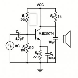
This simple audio amplifier uses an MJD31CT4 transistor. Let me break it down for you: your audio input first goes through a 4.7µF capacitor—this blocks any DC voltage and passes only the AC audio signals into the transistor’s base. Two resistors, 56kΩ and 10kΩ, set the transistor’s operating point, keeping it stable. A 220Ω resistor and 100µF capacitor provide feedback, helping smooth and stabilize the amplified signal. Finally, the amplified audio signal passes through a 1kΩ resistor and a 10µF capacitor, filtering out DC and ensuring clear audio reaches your speaker.
mjd31ct4 transistor application
The MJD31CT4 transistor is pretty versatile. If you’re making a small audio amplifier, it’ll boost the sound nicely for clearer audio in speakers or portable gadgets. You can also use it to drive things like DC motors, relays, or even pumps in your toys or fans. It works great controlling LED lights or bulbs, too, giving a stable output. Just be careful about heat—use proper cooling to avoid damaging it, keep within its rated current and voltage, and if your load has coils like motors or relays, always add a diode to prevent voltage spikes.
More Like This

MMBT5550LT1G
onsemi

MMBT2222A
HY Electronic (Cayman) Limited
MMBT3904
HY Electronic (Cayman) Limited
MMBT2907A
HY Electronic (Cayman) Limited

TIP41C
Fairchild Semiconductor

PMBT3904,215
NXP Semiconductors

TIP120
Central Semiconductor Corp

TIP36C
Central Semiconductor Corp
TIP35C
Central Semiconductor Corp

TIP3055
Central Semiconductor Corp
TIP2955
Central Semiconductor Corp
TIP147
Central Semiconductor Corp
Also Add to Cart
BU508A
STMicroelectronics

MMBT4401LT1G
onsemi

2SC4617TLQ
Rohm Semiconductor

TIP3055
STMicroelectronics
TIP147
Central Semiconductor Corp

BC857BW
Yangzhou Yangjie Electronic Technology Co.,Ltd

BC817-40,215
Nexperia USA Inc.

TIP120
onsemi

NJT4030PT1G
onsemi

2N3055
STMicroelectronics

MMBT3906
Diotec Semiconductor
BC846B
Diotec Semiconductor
Related Products
MMBT5550LT1G
onsemi
MMBT2222A
HY Electronic (Cayman) Limited
MMBT3904
HY Electronic (Cayman) Limited
MMBT2907A
HY Electronic (Cayman) Limited
TIP41C
Fairchild Semiconductor
PMBT3904,215
NXP Semiconductors
TIP120
Central Semiconductor Corp
TIP36C
Central Semiconductor Corp
TIP35C
Central Semiconductor Corp
TIP3055
Central Semiconductor Corp
TIP2955
Central Semiconductor Corp
TIP147
Central Semiconductor Corp
TIP142
Central Semiconductor Corp

2N2369AUB
Microchip Technology
BCX17
onsemi

BCP69
onsemi
BCP53
onsemi
PZT2907A
onsemi

2SC5200
STMicroelectronics

2N2907A
Micro Commercial Co
BCP52-16
STMicroelectronics

MMBTA92
STMicroelectronics
2N3773
STMicroelectronics
,TO-226_straightlead.jpg "2N5551")
2N5551
onsemi
MPSA92
onsemi
MPS751G
onsemi

MJD44H11
onsemi
MJD127
onsemi

2SC4617
onsemi
TIP42C
onsemi
Please send RFQ , we will respond immediately.
