
MB6S Bridge Rectifier | Datasheet, Pinout, Circuit Diagram & Specifications
- Voltage-PeakReverse(Max): 600 V
- Current-AverageRectified(Io): 500 mA
- Voltage-Forward(Vf)(Max)@If: 1 V @ 500 mA
- Package: TO-269AA, 4-BESOP


FREE delivery for orders over HK$250.00

Quick response, quick quotaton

Flash shipment,no worries after sales

Original channel,guarantee of the authentic products
diode mb6S
Mb6s Pinout

Mb6s Pinout Diagram
The MB6S is a commonly used bridge rectifier, typically employed in power conversion circuits to convert AC to DC. Here’s a brief description of its pinout:
| Pin Number | Pin Description | Explanation |
|---|---|---|
| 1 | Anode (+) | Connected to the positive side of the circuit, typically for power or signal input. |
| 2 | Cathode (-) | Connected to the negative side of the circuit, acting as the negative voltage or signal output. |
| 3 | Anode (+) | Another anode pin, can be used for parallel connections to enhance current handling capabilities. |
| 4 | Cathode (-) | Another cathode pin, works with Pin 2 to provide full rectification function for the diode. |
The MB6S bridge rectifier effectively converts AC to DC using its four pins, which manage the AC input and output the corresponding DC voltage. This makes it a critical component in power electronics, ensuring smooth and stable DC power output for a variety of devices.
MB6S Circuit Diagram
mb6s is a rectifier bridge chip, its role is to use the diode’s unidirectional conduction characteristics, will be converted to DC power. mb6s chip package form SOP-4 chip package, pin spacing is 2.5mm. package material for the epoxy. As shown in the figure, the left figure is the physical picture, the right figure is the internal structure.
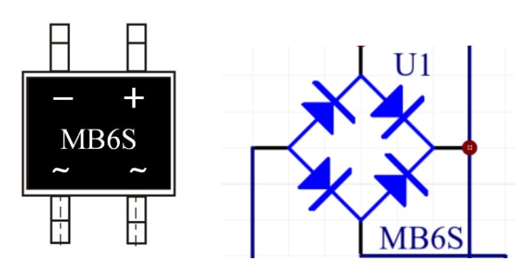
On the surface of the chip, marked with a wavy line of the two pins for the AC voltage input pin, the other two pins for the DC voltage output pin, its internal rectifier circuit is composed of four rectifier diodes, this is the circuit schematic diagram, in order to get a smoother DC output, we generally external to the output side of a filter capacitor. Its working principle is very simple, we assume that the load for a small lamp, then, when the alternating current is in a certain half-cycle, the current path is such as shown in the figure.

When the alternating current is in the other half of the cycle, the current path is then shown in the figure.

The final effect is that the output produces a positive voltage output at each half cycle of the AC voltage. The final result is a smoothed voltage that is optimized by the capacitor.
Compared with the same series MB10S, from the specifications of the two compared to the parameters, we can see that in addition to the reverse withstand voltage is not the same, other than the same, the reverse withstand voltage MB6S is 600 volts, the reverse withstand voltage of the MB10S is 1000 volts. Chip rectifier bridge due to the characteristics of the package volume would have been used in low-power equipment, low-power general voltage requirements do not need to be so high, too high a value of the withstand voltage instead of a waste, and from the point of view of the cost of speaking MB6S is more cost-effective, so the majority of low-power equipment are used MB6S.
More Like This

IPD95R750P7
Infineon Technologies

IPW65R050CFD7A
Infineon Technologies

PMV48XPA
Nexperia

IPG20N04S4-08
Infineon Technologies
BUK9Y3R5-40E
Nexperia

BSC059N04LS G
Infineon Technologies
PMGD280UN
Nexperia
IPW90R500C3
Infineon Technologies

IPA80R450P7
Infineon / IR
BSC360N15NS3 G
Infineon Technologies

SPA15N65C3
Infineon Technologies
IPA60R400CE
Infineon Technologies
Also Add to Cart

NVATS5A114PLZT4G
onsemi

MB10F
SMC Diode Solutions

CSD17381F4
Texas Instruments

IRLB8314PBF
Infineon Technologies

MMSZ5245B
Shenzhen Slkormicro Semicon Co., Ltd.

STW12N120K5
STMicroelectronics

IRFP3306PBF
International Rectifier

C3M0075120K
Wolfspeed, Inc.

SI2307BDS-T1-E3
Vishay Siliconix

KBPC3510
Solid State Inc.

IRFS4115TRLPBF
Infineon Technologies

MBR2045CT
Solid State Inc.
Related Products
IPD95R750P7
Infineon Technologies
IPW65R050CFD7A
Infineon Technologies
PMV48XPA
Nexperia
IPG20N04S4-08
Infineon Technologies
BUK9Y3R5-40E
Nexperia
BSC059N04LS G
Infineon Technologies
PMGD280UN
Nexperia
IPW90R500C3
Infineon Technologies
IPA80R450P7
Infineon / IR
BSC360N15NS3 G
Infineon Technologies
SPA15N65C3
Infineon Technologies
IPA60R400CE
Infineon Technologies
SPA17N80C3
Infineon Technologies
IPW60R017C7
Infineon Technologies
SPW35N60CFD
Infineon Technologies
IPD50N04S4-10
Infineon Technologies
IPW90R120C3
Infineon Technologies
L2N7002DW1T1G
onsemi
TK49N65W5
Toshiba
PSMN2R0-30YLE
Nexperia

IRLML9301
Infineon Technologies
IPP60R160P7
Infineon Technologies

BSG0810NDI
Infineon Technologies
2SK3565
Toshiba
BSC027N10NS5
Infineon Technologies
IRF2807
Infineon / IR
BSH203
Nexperia

IPZ40N04S5L-4R8
Infineon Technologies
IPP60R099CP
Infineon Technologies
IPP65R190CFD
Infineon Technologies
Please send RFQ , we will respond immediately.
