MB10S Bridge Rectifier | Datasheet, Price & PDF | Diode & Circuit Information
- Voltage-PeakReverse(Max): 1 kV
- Current-AverageRectified(Io): 500 mA
- Voltage-Forward(Vf)(Max)@If: 1 V @ 500 mA
- Current-ReverseLeakage@Vr: 5 µA @ 1000 V
- Price: inquiry

MB10S Bridge Rectifier Circuit Diagram

mb10s bridge rectifier circuit diagram
What is a rectifier bridge and what does it do:
Rectifier bridge is composed of four diodes connected in parallel two by two, can be AC input into DC output device, mainly used in the need for AC input places, such as zero-fire switch, household large electrical appliances and so on.
Principle of operation:
The principle is to use the diode’s unidirectional conduction characteristics, will be converted to direct current alternating current. When the input AC power becomes a positive half cycle,, and the current flows from the positive pole to the negative pole; when the input alternating current is in the negative half cycle, the other two opposite diodes conduct, and the current flows from the negative pole to the positive pole. By alternating the conduction, the rectifier bridge can convert AC power to DC power.
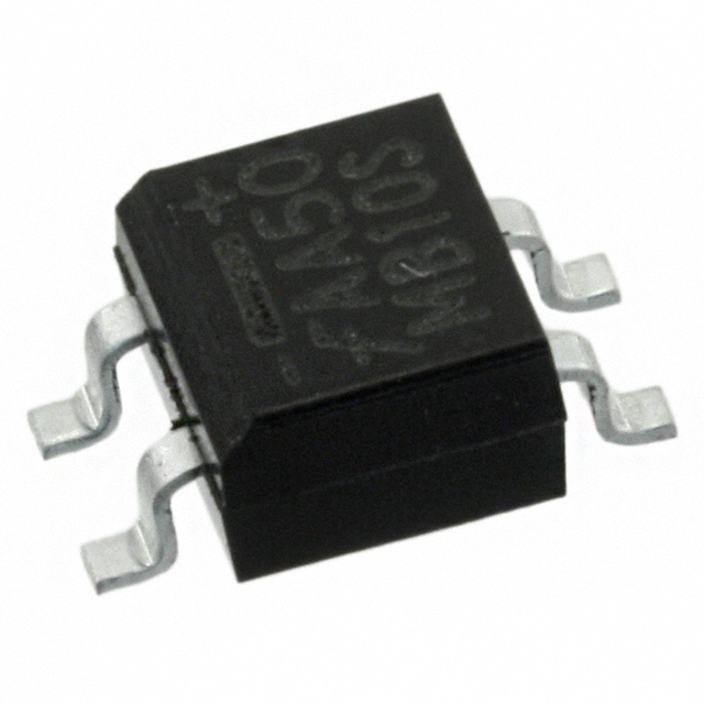
MB10S is a small chip-type bridge rectifier, widely used in a variety of electronic devices will be converted from AC to DC output. MB10S application circuit as shown in the figure, the left is a two-wave line represents the AC input is generally connected directly to the AC through the protection circuit (the protection circuit is generally composed of fuses, diodes and other devices); the right side of a + and – represent the DC output of the positive and negative terminals, respectively. positive and negative poles respectively. After the MB10S output DC voltage is generally not very stable there may be a lot of burrs, this time we generally connect an aluminium electrolytic capacitor in parallel with the output (pay attention to the value of the withstand voltage, try to select the withstand voltage value of large such as 400V withstand voltage) to absorb the burrs part of the output to make the output more stable and also to avoid the burrs to avoid the breakdown of the back-end circuits.
Design circuit notes: the main attention to the selection of each component, to achieve a large value of the withstand voltage, as far as possible to leave a margin of 20 per cent (for example, after the MB10S voltage of 220V, then the capacitor’s withstand voltage value should be 220/0.8 = 275V, we choose 400V is absolutely enough); but also to pay attention to the MB10S heat dissipation, because of a large amount of current flow and diode Rapid opening and closing of the diode will produce a lot of heat, if the temperature exceeds the junction temperature of the device will lead to the device is burned, resulting in the impact of the back stage circuit.
More Like This

MMBFJ177
onsemi

MMBFJ176
Rochester Electronics, LLC
MMBFJ177
Rochester Electronics, LLC

NSVJ3557SA3T1G
onsemi
MMBFJ112
onsemi
MMBFJ113
onsemi
MMBFJ201
onsemi

MMBF4392LT1G
onsemi,Rochester Electronics, LLC
MMBF4393LT1G
onsemi
MMBFJ176
onsemi

JFE150DCKR
Texas Instruments
MMBFJ177LT1G
onsemi
Also Add to Cart

STPS2L60A
STMicroelectronics

STP4N150
STMicroelectronics

IRFP4868PBF
Infineon Technologies

FDG6332C
onsemi

MA4E2037
MACOM Technology Solutions

FCB070N65S3
onsemi

MUN5214DW1T1G
onsemi

IRGP30B120KD-EP
Infineon Technologies

1N4007
Micro Commercial Co

STH315N10F7-2
STMicroelectronics

MBR40250G
Rochester Electronics, LLC,onsemi

AONR36366
Alpha & Omega Semiconductor Inc.
MMBFJ177
onsemi
MMBFJ176
Rochester Electronics, LLC
MMBFJ177
Rochester Electronics, LLC
NSVJ3557SA3T1G
onsemi
MMBFJ112
onsemi
MMBFJ113
onsemi
MMBFJ201
onsemi
MMBF4392LT1G
onsemi,Rochester Electronics, LLC
MMBF4393LT1G
onsemi
MMBFJ176
onsemi