
MAX485ED datasheet | price | pdf
- Type: Transceiver
- Protocol: RS422, RS485
- Data Rate: 5Mbps
- Package: 8-SOIC (0.154", 3.90mm Width)


FREE delivery for orders over HK$250.00

Quick response, quick quotaton

Flash shipment,no worries after sales

Original channel,guarantee of the authentic products
MAX485ED
The MAX485ED is a chip designed specifically for RS-485 communication. Simply put, it helps convert signals between TTL and RS-485 levels. For example, if you want to use a microcontroller (which usually outputs TTL signals) to control industrial equipment or transmit data, you’ll need the MAX485ED to handle that conversion.
MAX485ED usually comes in an SOIC-8 surface-mount package, making it easy to solder and integrate into various designs. If you’re working on automation equipment, industrial communication systems, measurement instruments, or data acquisition setups, this chip is definitely a good choice.
MAX485ED pinout

| Pin No. | Pin Name | Description |
|---|---|---|
| 1 | RO | Receiver Output |
| 2 | RE̅ | Receiver Enable (Active LOW) |
| 3 | DE | Driver Enable (Active HIGH) |
| 4 | DI | Driver Input |
| 5 | GND | Ground |
| 6 | A | RS-485 Differential Signal (Positive) |
| 7 | B | RS-485 Differential Signal (Negative) |
| 8 | VCC | Power Supply (+5V) |
Make sure to properly configure sending and receiving modes for smooth communication. Additionally, in industrial environments, using shielded twisted-pair cables can significantly improve signal reliability and noise resistance.
MAX485ED equivalent rs485 chip

| Model | Manufacturer | Package | Voltage | Data Rate | ESD Protection | Typical Current | Features |
|---|---|---|---|---|---|---|---|
| MAX485ED | HTC Korea | SOIC-8 | 5V | 2.5 Mbps | ±15 kV | 500 µA | Low-power, half-duplex, ±15 kV ESD protection |
| ADM485ARMZ | Analog Devices | SOIC-8 | 5V | 2.5 Mbps | ±15 kV | 500 µA | Low-power, half-duplex, ±15 kV ESD protection |
| SN75176BPE4 | Texas Instruments | SOIC-8 | 5V | 10 Mbps | ±15 kV | 500 µA | High-speed, half-duplex, ±15 kV ESD protection |
| AM26LS31CN | Texas Instruments | SOIC-8 | 5V | 10 Mbps | ±15 kV | 500 µA | High-speed, half-duplex, ±15 kV ESD protection |
| XY-K485 | XY Electronics | SOIC-8 | 5V | 2.5 Mbps | ±15 kV | 500 µA | TTL to RS-485 with automatic direction control |
Important Considerations for Choosing a Replacement:
-
Electrical Compatibility:
Make sure the operating voltage, data rate, and ESD protection levels of the replacement chip match the requirements of your original design. -
Functional Matching:
Check if the replacement chip supports half-duplex communication with the same DE and RE control logic as the MAX485ED. -
Package Consistency:
Although all listed chips have an SOIC-8 package, carefully verify pin functions using datasheets, as slight variations can exist.
MAX485ED rs485 communication circuit
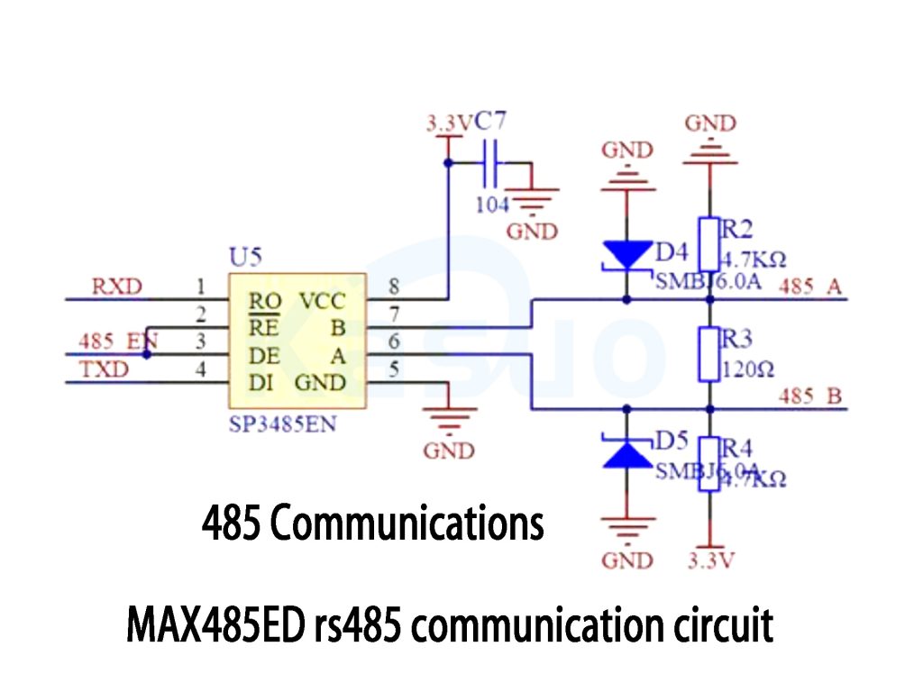
This circuit uses the SP3485EN chip for RS-485 communication, acting as a bridge for microcontrollers like STM32 or Arduino to communicate with external RS-485 devices.
First, let’s break down the chip connections:
-
The chip’s RO pin is connected to the microcontroller’s RXD pin, which receives data from other devices on the RS-485 bus.
-
The RE̅ and DE pins are tied together and controlled by a signal labeled 485_EN. When 485_EN is high, the chip goes into transmission mode; otherwise, it stays in reception mode.
-
The DI pin connects directly to the microcontroller’s TXD pin and is used to send data.
-
The chip’s VCC pin is powered by 3.3V, and GND pin is grounded.
Next, let’s look at the RS-485 bus interface (lines A and B):
-
The A and B lines carry differential signals and connect directly to the RS-485 bus.
-
The resistor labeled R3 (120Ω) is crucial, typically placed at each end of the bus to prevent signal reflections and ensure stable communication.
Some protective components are also included:
-
TVS diodes (D4 and D5, SMBJ6.0A) protect the chip from voltage spikes, such as those caused by static electricity.
-
Two 4.7kΩ resistors (R2 and R4) pull the lines to 3.3V and GND, respectively, to establish a stable reference voltage, preventing signal drifting when the bus is idle.
MAX485ED bus termination resistor
MAX485ED typically uses a 120Ω termination resistor for impedance matching in RS-485 bus applications.
Purpose of the Termination Resistor:
RS-485 utilizes differential signaling, and placing a 120Ω resistor at the bus termination points matches the characteristic impedance of the bus. This helps prevent signal reflections during transmission and enhances the stability and reliability of data transfer.
Connection Method of Termination Resistors:
Typically, a 120Ω termination resistor is connected across the bus lines at each end of the RS-485 network.
Intermediate nodes usually do not require additional termination resistors.
MAX485ED pcb layout guidelines
When designing a PCB layout for the MAX485ED, there are some important details to pay attention to—after all, good details mean more stable communication.
First, always place a decoupling capacitor (usually a 0.1μF SMD capacitor) as close as possible to the chip’s power pin. This helps filter out small interferences in the power supply.
Next, make sure the RS-485 signal lines (A and B) are routed side by side as differential pairs. Try to keep their lengths equal to prevent signal delays or distortion. If you approach the layout using the idea of twisted-pair wiring, you’ll get even better noise immunity.
Also, terminal resistors are very important. Typically, you only need to place a 120Ω resistor at each end of the bus—no need to add resistors at intermediate nodes. This helps prevent signal reflections and ensures clearer data transmission.
More Like This

ISL99227FRZ-TR5784
Renesas Electronics America Inc

ISL99227HRZ-TR5784
Renesas Electronics America Inc

ISL99227BFRZ-TR5784
Renesas Electronics America Inc

ISL99360HRZ-TS2794
Renesas Electronics America Inc

ISL99227BFRZ-TR5783
Renesas Electronics America Inc

ISL99227BFRZ-TR5782
Renesas Electronics America Inc

ISL99227HRZ-TR5783
Renesas Electronics America Inc

ISL99227FRZ-TR5783
Renesas Electronics America Inc

ISL99227FRZ-TR5782
Renesas Electronics America Inc

ISL99227HRZ-TR5782
Renesas Electronics America Inc
WIZ750SR-DBL
WIZnet

W7500S2E-R1
WIZnet
Also Add to Cart

LTC4015EUHF#TRPBF
Analog Devices Inc.

DS1339U-33+T&R
Analog Devices Inc./Maxim Integrated

MCP3204-BI/SL
Microchip Technology
LMC7660IMX/NOPB
Texas Instruments

ADS1298CZXGR
Texas Instruments

TPS25910RSAR
Texas Instruments

TPS26633RGER
Texas Instruments

NCP584HSN33T1G
onsemi

INA230AIRGTR
Texas Instruments
_4040208^C.jpg "TPS75825KC")
TPS75825KC
Texas Instruments

THGBMJG8C4LBAU8
Kioxia America, Inc.

TPS3431SDRBR
Texas Instruments
Related Products
ISL99227FRZ-TR5784
Renesas Electronics America Inc
ISL99227HRZ-TR5784
Renesas Electronics America Inc
ISL99227BFRZ-TR5784
Renesas Electronics America Inc
ISL99360HRZ-TS2794
Renesas Electronics America Inc
ISL99227BFRZ-TR5783
Renesas Electronics America Inc
ISL99227BFRZ-TR5782
Renesas Electronics America Inc
ISL99227HRZ-TR5783
Renesas Electronics America Inc
ISL99227FRZ-TR5783
Renesas Electronics America Inc
ISL99227FRZ-TR5782
Renesas Electronics America Inc
ISL99227HRZ-TR5782
Renesas Electronics America Inc
WIZ750SR-DBL
WIZnet
W7500S2E-R1
WIZnet

W5500S2E-Z1
WIZnet

W5500S2E-S1
WIZnet

NM7010B+
WIZnet
APEHC-D40
Apacer Memory America
APEHC-D30
Apacer Memory America
APEHC-D10
Apacer Memory America
APEFC-R50
Apacer Memory America
APEFC-R40
Apacer Memory America
APEFC-R30
Apacer Memory America
APEFC-R10
Apacer Memory America
APEFC-G50
Apacer Memory America
APEFC-G40
Apacer Memory America
APEFC-G30
Apacer Memory America
APEFC-G10
Apacer Memory America
APEFC-D50
Apacer Memory America
MTIFM.R3-SP
Multi-Tech Systems Inc.
MTIFM.R3
Multi-Tech Systems Inc.
50040R-02
Echelon Corporation
Please send RFQ , we will respond immediately.
