
MAX3421EETJ+T datasheet, price | pdf
- Brands: Analog Devices Inc./Maxim Integrated
- Download: MAX3421EETJ+T Datasheet PDF
- Price: inquiry
- In Stock: 5,937
- Protocol: USB
- Function: Controller
- Interface: SPI
- Package: 32-WFQFN Exposed Pad


FREE delivery for orders over HK$250.00

Quick response, quick quotaton

Flash shipment,no worries after sales

Original channel,guarantee of the authentic products
MAX3421EETJ Pinout Equivalent Circuit
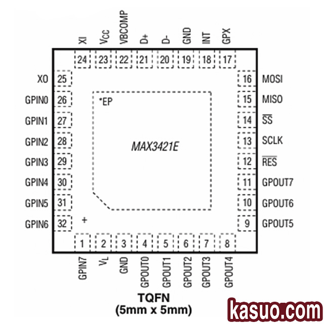
MAX3421EETJ is a USB peripheral/host controller launched by Analog Devices, which adopts VQFN-32-EP (5×5), integrates USB transmitter and SIE (Serial Interface Engine), communicates with the host controller through SPI interface, complies with USB2.0 specification, and supports full speed 12Mbps peripheral mode and full/low-speed 12Mbps/1.5Mbps host mode. The chip also integrates a level converter, which can operate at voltages ranging from 1.4V to 3.6V. It is often used in embedded systems, instruments, medical devices, and other applications that require USB communication.
Pin definition:
| PIN | Name | FUNCTION |
|---|---|---|
| 1 | GPIN7 | Input pin, provide pull-up resistor connected to VL. |
| 2 | VL | The voltage input pin for level conversion is connected to a voltage source ranging from 1.4V to 3.6V. |
| 3, 19 | GND | Grounding pin. |
| 4~11 | GOUT0~GOUT7 | Universal push-pull output, logic level reference VL voltage. |
| 12 | RES | Reset pin low level is effective, clearing internal register parameters. |
| 13 | SCLK | SPI clock input (up to 26MHz), rising edge input data, falling edge output data. |
| 14 | SS | SPI chip selection input, low level effective. |
| 15 | MISO | SPI data output (main input and output), push-pull output. |
| 16 | MOSI | SPI data input (master output slave input) or bidirectional mode. |
| 17 | GPX | Programmable multiplexed output, signal type can be configured through PINCTL register. |
| 18 | INT | Interrupt output, edge mode is push-pull, level mode is open drain low effective. |
| 20 | D- | USB D-signal requires a 33 Ω resistor in series, with an internal 15k Ω pull-down resistor. |
| 21 | D+ | The USB D+ signal requires a 33 Ω resistor to be connected in series, which includes a 1.5k Ω pull-up resistor and a 15k Ω pull-down resistor. |
| 22 | VBCOMP | VBUS comparator input, used to detect power status. |
| 23 | VCC | The power input is generally 3.3V. |
| 24 | XI | Connect the input pins of the crystal oscillator. |
| 25 | XO | Connect the output pins of the crystal oscillator. |
| 26~32 | GPIN0~GPIN66 | Universal input pins. |
Alternative model selection:
When choosing an alternative model for MAX3421EETJ, the following key aspects need to be considered to ensure that the new device can meet the original design requirements and achieve a perfect replacement as much as possible. The consistency of functionality is the most important, and it needs to be confirmed whether the replacement chip can achieve USB host/peripheral control like MAX3421EETJ, supporting the same USB protocol and data transfer rate. The second is the interface type, ensuring that the new device provides interfaces compatible with the existing system, such as SPI, I ² C, or UART, which can facilitate communication with the main controller. The third is the packaging form. If you do not want to change the original PCB shape and design, you need to determine whether the substitute chip model can be consistent with the existing one.
| Picture | Name | Interface Type | Support Agreement | Working Voltage | Package |
|---|---|---|---|---|---|
 |
MAX3421E | SPI | USB 2.0 Host/Peripheral | 3.0V-3.6V | TQFP-32 |
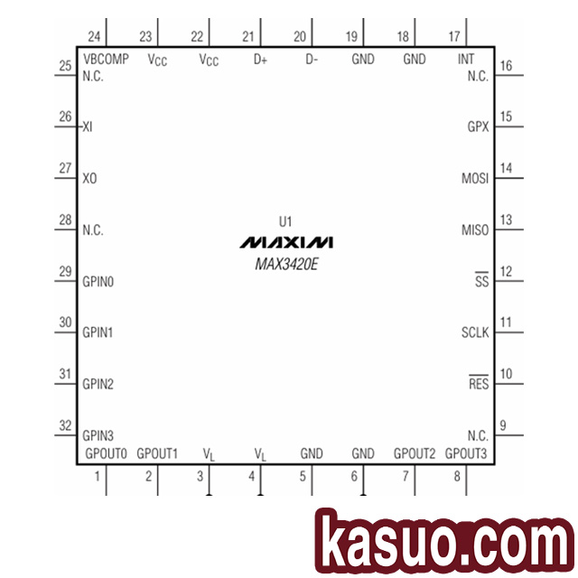 |
MAX3420E | SPI | USB 2.0 (full speed working mode) | 3.0V-3.6V | TQFP-32 |
 |
VNC1L | UART/SPI | USB 2.0 Host/Peripheral | 3V ~ 3.6V | LQFP-48 |
 |
VNC2 | UART/SPI | USB 2.0 Host/Peripheral | 1.8V/3.3V | LQFP-48/QFN-64 |
Typical Applications:

Design application circuit diagram
The design in the diagram is mainly divided into four modules. Power circuit design, USB interface design, clock circuit design, and microcontroller SPI interface design.
The power circuit design mainly includes a MAX6349TL low dropout regulator that converts the 5V input from the USB port to 3.3V, providing power for the microcontroller and MAX3421EETJ.
The USB interface circuit is connected to the D+and D – pins of MAX3421EETJ through a 33 ohm resistor. When drawing the PCB later, attention should be paid to impedance matching and differential wiring. It also provides a voltage detection system that monitors the voltage provided by the USB port in real-time, serving to protect the circuit.
More Like This

CBTL06GP213EE
NXP Semiconductors

MAX458EPL
Analog Devices / Maxim Integrated
ADG5412FBCPZ
Analog Devices
ADG5412BFBCPZ
Analog Devices
ADG854BCPZ
Analog Devices
DG187AA
Vishay / Siliconix

74LVC1G66GV
Nexperia
FSA2275A
onsemi
TC4066BP
Toshiba
74LVC2G66DP
Nexperia
74LVC1G66GW
Nexperia
ADG1414BCPZ
Analog Devices
Also Add to Cart

S25FL128SAGBHIA13
Cypress Semiconductor Corp

ESD7104MUTAG
onsemi
74LVC1G00GV
Nexperia
MIC29300-5.0WU
Microchip Technology

EPF10K50RC240-4
Intel
AD7276BUJZ
Analog Devices

TPS22860DBVR
Texas Instruments

MAX232CWE
Analog Devices Inc./Maxim Integrated

FT230XQ-T
FTDI, Future Technology Devices International Ltd

5CGXFC3B7F23C8N
Intel

STR-A6053M
Sanken

MAX705CSA
Analog Devices Inc./Maxim Integrated
Related Products
CBTL06GP213EE
NXP Semiconductors
MAX458EPL
Analog Devices / Maxim Integrated
ADG5412FBCPZ
Analog Devices
ADG5412BFBCPZ
Analog Devices
ADG854BCPZ
Analog Devices
DG187AA
Vishay / Siliconix
74LVC1G66GV
Nexperia
FSA2275A
onsemi
TC4066BP
Toshiba
74LVC2G66DP
Nexperia
74LVC1G66GW
Nexperia
ADG1414BCPZ
Analog Devices

MAX4649EKA
Analog Devices / Maxim Integrated
74HC1G66GW
Nexperia
74LVC4066PW
Nexperia
ADG702BRTZ
Analog Devices
ADG701BRTZ
Analog Devices

ADG1219BRJZ
Analog Devices

74HCT4066D
Nexperia
ADG819BRTZ
Analog Devices
HEF4066BT
Nexperia

74HC4066PW
Nexperia
ADG1436YCPZ
Analog Devices
74HC1G66GV
Nexperia
ADG802BRTZ
Analog Devices
CLC018AJVJQ
Texas Instruments
HEF4014BT
Nexperia

74HCT165D
Nexperia

MC14094BCP
onsemi
74HCT164D
Nexperia
Please send RFQ , we will respond immediately.
