
MAX3243EIPW datasheet | price & pdf
- Type: Transceiver
- Protocol: RS232
- Number of Drivers/Receivers: 3/5
- Package: 28-TSSOP (0.173, 4.40mm Width)


FREE delivery for orders over HK$250.00

Quick response, quick quotaton

Flash shipment,no worries after sales

Original channel,guarantee of the authentic products
MAX3243EIP serial communication ic
The MAX3243EIP is a handy RS-232 transceiver chip made by Maxim Integrated. It lets you set up standard RS-232 communication easily, using just one single power supply (anywhere from 3.0 to 5.5 volts). One of the best things about this chip is that it has a built-in charge pump, meaning you don’t need extra components to boost voltage, which simplifies your circuit design.
It’s ideal for devices where low power consumption and reliable operation matter—like portable electronics, industrial controls, or communication systems. Plus, it’s built to handle tough conditions, thanks to its robust ±15kV ESD protection, keeping your equipment safe from static damage.
MAX3243EIP pinout

| Pin Number | Pin Name | Type | Description |
| 1 | C2+ | — | Positive terminal of charge-pump capacitor C2 |
| 2 | C2− | — | Negative terminal of charge-pump capacitor C2 |
| 3 | V− | O | Negative voltage output from charge pump |
| 4 | RIN1 | I | RS-232 Receiver input 1 |
| 5 | RIN2 | I | RS-232 Receiver input 2 |
| 6 | RIN3 | I | RS-232 Receiver input 3 |
| 7 | RIN4 | I | RS-232 Receiver input 4 |
| 8 | RIN5 | I | RS-232 Receiver input 5 |
| 9 | DOUT1 | O | RS-232 Driver output 1 |
| 10 | DOUT2 | O | RS-232 Driver output 2 |
| 11 | DOUT3 | O | RS-232 Driver output 3 |
| 12 | DIN3 | I | Driver input 3 (from UART) |
| 13 | DIN2 | I | Driver input 2 (from UART) |
| 14 | DIN1 | I | Driver input 1 (from UART) |
| 15 | ROUT5 | O | Receiver output 5 (to UART) |
| 16 | ROUT4 | O | Receiver output 4 (to UART) |
| 17 | ROUT3 | O | Receiver output 3 (to UART) |
| 18 | ROUT2 | O | Receiver output 2 (to UART) |
| 19 | ROUT1 | O | Receiver output 1 (to UART) |
| 20 | ROUT2B | O | Always-active, non-inverted output for RIN2 |
| 21 | INVALID | O | INVALID output indicator pin |
| 22 | FORCEOFF | I | Automatic power-off control input |
| 23 | FORCEON | I | Automatic power-on control input |
| 24 | C1− | — | Negative terminal of charge-pump capacitor C1 |
| 25 | GND | — | Ground |
| 26 | VCC | — | Power supply input (3.0 V to 5.5 V) |
| 27 | V+ | — | Positive voltage output from charge pump |
| 28 | C1+ | — | Positive terminal of charge-pump capacitor C1 |
This pin configuration applies to MAX3243EIP in SSOP, SOIC, and TSSOP packages.
MAX3243EIP equivalent ic
| Model | Manufacturer | Key Features |
| SP3243E | MaxLinear | 3 drivers / 5 receivers, Auto On-Line®, 1Mbps data rate, ±15kV ESD protection, 3.0V–5.5V supply |
| XR32431 | MaxLinear | 3 drivers / 5 receivers, 1.65V–5.5V logic interface, Auto On-Line®, up to 1Mbps, ±15kV ESD protection |
| MAX3243E | Analog Devices | Same as MAX3243EIP; available in various packages |
| MAX3232 | Texas Instruments | 2 drivers / 2 receivers, 3.0V–5.5V supply, ±15kV ESD protection, up to 250kbps data rate |
SP3243E: A direct replacement with similar features, including Auto On-Line® and high-speed operation.
XR32431: Offers a wider logic interface voltage range (1.65V–5.5V), making it suitable for systems with lower voltage logic levels.
MAX3243E: Identical functionality; consider different package options if needed.
MAX3232: Suitable for applications requiring fewer channels (2 drivers / 2 receivers).
MAX3243EIP rs232 circuit example
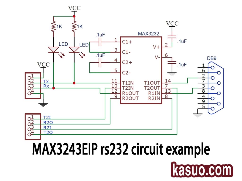
This circuit uses a MAX3232 chip, which is very similar to MAX3243, to convert signals between RS-232 (common in older serial devices) and modern TTL logic (used in microcontrollers and digital circuits).
The chip takes care of converting the lower-voltage signals from a microcontroller (usually 3.3V or 5V) to the higher voltage signals (±12V) needed by the RS-232 standard. It has built-in charge pumps that use external capacitors (four 0.1µF capacitors here) to generate these voltage levels.You see those four capacitors connected around pins 1, 3, 4, 5, 2, and 6? They help the chip internally boost the voltage. This means you don’t need a separate high-voltage supply; the chip creates it internally using just your regular 3.3V or 5V supply.There are two main signal lines from the microcontroller side: “Tx” (transmit) and “Rx” (receive). These signals go into the chip and come out as T1OUT and R1IN, which are connected to pins 2 and 3 on the DB9 connector—this is a standard connector for RS-232 communications.
All in all, it’s a great choice when you need dependable RS-232 connectivity without the hassle of complicated circuitry.
More Like This

ISL99227FRZ-TR5784
Renesas Electronics America Inc

ISL99227HRZ-TR5784
Renesas Electronics America Inc

ISL99227BFRZ-TR5784
Renesas Electronics America Inc

ISL99360HRZ-TS2794
Renesas Electronics America Inc

ISL99227BFRZ-TR5783
Renesas Electronics America Inc

ISL99227BFRZ-TR5782
Renesas Electronics America Inc

ISL99227HRZ-TR5783
Renesas Electronics America Inc

ISL99227FRZ-TR5783
Renesas Electronics America Inc

ISL99227FRZ-TR5782
Renesas Electronics America Inc

ISL99227HRZ-TR5782
Renesas Electronics America Inc
WIZ750SR-DBL
WIZnet

W7500S2E-R1
WIZnet
Also Add to Cart

OPA2836IRUNR
Texas Instruments

FP6373AS6CTR
Fitipower Integrated Tech

PIC16F946-I/PT
Microchip Technology

MAX1698EUB+T
Analog Devices Inc./Maxim Integrated

JS28F640J3F75A
Micron Technology Inc.

LT1963AES8-3.3
Analog Devices Inc.
PIC16F1823T-I/SL
Microchip Technology

MPQ2166AGRHE-AEC1-Z
Monolithic Power Systems Inc.

RT8077GQW
Richtek USA Inc.

AD534TE/883B
Analog Devices Inc.

TPS7A8801RTJR
Texas Instruments
MPC860DTCZQ50D4
NXP USA Inc.
Related Products
ISL99227FRZ-TR5784
Renesas Electronics America Inc
ISL99227HRZ-TR5784
Renesas Electronics America Inc
ISL99227BFRZ-TR5784
Renesas Electronics America Inc
ISL99360HRZ-TS2794
Renesas Electronics America Inc
ISL99227BFRZ-TR5783
Renesas Electronics America Inc
ISL99227BFRZ-TR5782
Renesas Electronics America Inc
ISL99227HRZ-TR5783
Renesas Electronics America Inc
ISL99227FRZ-TR5783
Renesas Electronics America Inc
ISL99227FRZ-TR5782
Renesas Electronics America Inc
ISL99227HRZ-TR5782
Renesas Electronics America Inc
WIZ750SR-DBL
WIZnet
W7500S2E-R1
WIZnet

W5500S2E-Z1
WIZnet

W5500S2E-S1
WIZnet

NM7010B+
WIZnet
APEHC-D40
Apacer Memory America
APEHC-D30
Apacer Memory America
APEHC-D10
Apacer Memory America
APEFC-R50
Apacer Memory America
APEFC-R40
Apacer Memory America
APEFC-R30
Apacer Memory America
APEFC-R10
Apacer Memory America
APEFC-G50
Apacer Memory America
APEFC-G40
Apacer Memory America
APEFC-G30
Apacer Memory America
APEFC-G10
Apacer Memory America
APEFC-D50
Apacer Memory America
MTIFM.R3-SP
Multi-Tech Systems Inc.
MTIFM.R3
Multi-Tech Systems Inc.
50040R-02
Echelon Corporation
Please send RFQ , we will respond immediately.
