KSZ8895MQXIA datasheet, price & pdf
- Protocol: Ethernet
- Function: Switch
- Interface: I²C, SPI
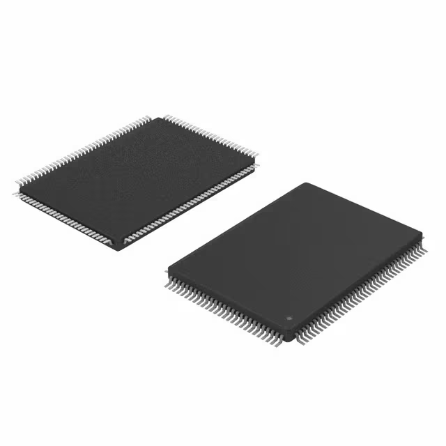
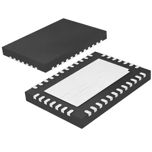
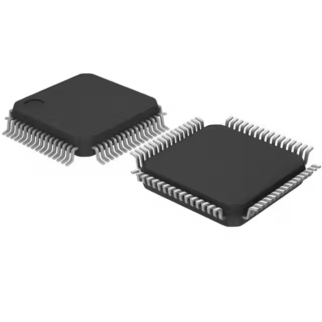
- Package: 128-BFQFP

FREE delivery for orders over HK$250.00

Quick response, quick quotaton

Flash shipment,no worries after sales

Original channel,guarantee of the authentic products
KSZ8895MQXIA Pinout Equivalent Circuit

1:Overview of the KSZ8895MQXIA:
The KSZ8895MQXIA is a high-performance 5-port Gigabit Ethernet switch controller developed by Microchip Technology. The KSZ8895MQXIA is widely used in embedded systems or network devices. It supports up to 5 ports for Gigabit Ethernet design, featuring low power consumption and high-speed data communication. It also offers functions such as VLAN, QoS, and traffic control. Under normal operating conditions, the current draw of the KSZ8895MQXIA is 100 mA. If battery power is used in the circuit, this device is an excellent choice. It supports RGMII/MII interfaces, allowing connection to main processors like ARM or FPGA. Additionally, the KSZ8895MQXIA handles VLAN tagging and CRC verification, and can perform port mirroring to reduce CPU load.
2:Pin function diagram of KSZ8895MQXIA:
| Pin Number | Pin Name | Type | Description & Note 2-4 | ||||||||||||||||||||||||
|---|---|---|---|---|---|---|---|---|---|---|---|---|---|---|---|---|---|---|---|---|---|---|---|---|---|---|---|
| 1 | MDI-XDIS | IPD | Disable auto MDI/MDI-X. Strap option: PD = (default) in normal operation. PU = disable auto MDI/MDI-X on all ports. |
||||||||||||||||||||||||
| 62 | PMRXD3 | IPD/O | PHY [5] MII receive bit 3. Strap option: PD = (default) enable flow control. PU = disable flow control. |
||||||||||||||||||||||||
| 63 | PMRXD2 | IPD/O | PHY [5] MII receive bit 2. Strap option: PD = disable back pressure. PU = enable back pressure. |
||||||||||||||||||||||||
| 64 | PMRXD1 | IPD/O | PHY [5] MII/RMII receive bit 1. Strap option: PD = drop excessive collision packets. PU = does not drop excessive collision packets. |
||||||||||||||||||||||||
| 65 | PMRXD0 | IPD/O | PHY [5] MII/RMII receive bit 0. Strap option: PD = disable aggressive back-off algorithm in half-duplex mode. PU = enable for performance enhancement. |
||||||||||||||||||||||||
| 66 | PMRXER | IPD/O | PHY [5] MII/RMII receive error. Strap option: PD = 1522/1518 bytes. PU = packet size up to 1536 bytes. |
||||||||||||||||||||||||
| 67 | PCRS | IPD/O | PHY [5] MII carrier sense. Strap option: PD = force half-duplex if auto-negotiation is disabled or fails. PU = force full-duplex if auto-negotiation is disabled or fails. |
||||||||||||||||||||||||
| 68 | PCCOL | IPD/O | PHY [5] MII collision detect. Strap option: PD = no force control. PU = force flow control. |
||||||||||||||||||||||||
| 80 | SMRXD3 | IPD/O | Switch MII receive bit 3. Strap option: PD = disable switch SW5-MII/RMII full-duplex flow control. PU = enable switch SW5-MII/RMII full-duplex flow control. |
||||||||||||||||||||||||
| 81 | SMRXD2 | IPD/O | Switch MII receive bit 2. Strap option: PD = switch SW5-MII/RMII in full-duplex mode. PU = switch SW5-MII/RMII in half-duplex mode. |
||||||||||||||||||||||||
| 82 | SMRXD1 | IPD/O | Switch MII receive bit 1. Strap option: PD = switch SW5-MII/RMII in 100 Mbps mode. PU = switch MII/RMII in 10 Mbps mode. |
||||||||||||||||||||||||
| 83 | SMRXD0 | IPD/O | Switch MII/RMII receive bit 0. Sivap option: LED mode PD (default) = mode 0; PU = mode 1. See “Register 11.”
|
||||||||||||||||||||||||
| 86 | SCONF1 | IPD |
Pin 91, 86, 87 are dual MII/RMII configuration pins for the Port 5 MAC 5 MII/RMII and PHY [5] MII/RMII. SWS-MII supports both MAC modes and PHY modes. P5-MII supports PHY mode only. See pins configuration below.
|
||||||||||||||||||||||||
| 87 | SCONF0 | IPD | Dual MII/RMII configuration pin. See Pin 86 description. | ||||||||||||||||||||||||
| 90 | LED5-2 | IPU/O | LED5 indicator 2. Strap option: Aging setup. See “Aging” section. PU = (default) aging enable; PD = aging disable. |
||||||||||||||||||||||||
| 91 | LED5-1 | IPU/O | LED5 indicator 1. Strap option: PU = (default) enable PHY [5] MII I/F. PD = Tri-state all PHY [5] MII output. See “Pin 86 SCONF1.” |
||||||||||||||||||||||||
| 92 | LED5-0 | IPU/O | LED5 indicator 0. Strap option for Port 4 only. PU = (default) enable auto-negotiation. PD = disable auto-negotiation.Strap to Register 76 bit [7]. |
||||||||||||||||||||||||
| 95 | LED4-0 | IPU/O | LED indicator 0. Strap option: PU = (default) in normal mode. PD = Energy Detection mode (EDPD mode). Strap to Register 14 bits [4:3]. |
||||||||||||||||||||||||
| 98 | LED3-0 | IPU/O | LED3 indicator 0. Strap option: PU (default) = Select I/O current drive strength (8 mA); PD = Select I/O current drive strength (12 mA). Strap to Register 132 bit [7:6] |
||||||||||||||||||||||||
| 101 | LED2-2 | IPU/O | LED2 indicator 2. Strap option for KSZ8895RXQ only: PU = (default) = Select the device as clock mode in RQX SW5-RMII, 25 MHz crystal to X1/X2 pins of the device and REFCLK output 50 MHz clock. PD = Select the device as normal mode in SW5-RMII. Switch MAC5 used only. The input clock is useless from X1/X2 pin, the device’s clock comes from SMTXCS/SMREFCLK pin, 50 MHz reference clock from external 50 MHz clock source. |
||||||||||||||||||||||||
| 102 | LED2-1 | IPU/O | LED2 indicator 1. Strap option for Port 3 only. PU = (default) = Enable auto-negotiation. PD = Disable auto-negotiation. Strap to Register50 bit [7]. |
||||||||||||||||||||||||
| 105 | LED1-0 | IPU/O | LED1 indicator 1. Strap option for Port 3 only. PU = (default) = no force flow control, normal operation. PD = force flow control. Strap to Register50 bit [4]. |
||||||||||||||||||||||||
| 106 | LED1-1 | IPU/O | LED1 indicator 0. Strap option for Port 3 only. PU = (default) = force half-duplex if auto-negotiation is disabled or fails. PD = force full-duplex if auto-negotiation is disabled or fails. Strap to Register50 bit [5]. |
||||||||||||||||||||||||
| 113 | PS1 | IPD |
Serial bus configuration pin. For this case, if the EEPROM is not present, the KSZ8895MQX/RQX/FXMII will start itself with the PS1[0] = 00 default register values.
|
||||||||||||||||||||||||
| 114 | PS0 | IPD | Serial bus configuration pin. See Pin 113. | ||||||||||||||||||||||||
| 12B | TEST2 | NC | NC for normal operation. Factory test pin. |
3:Partial circuit diagram of the KSZ8895MQXIA component.

(1)The diagram above shows a circuit using an internal 1.2V low-dropout (LDO) controller. This is the preferred circuit diagram that uses an internal 1.2V LDO controller along with an external MOSFET. The 1.2V rail from the MOSFET drain pin to VDDAR pin 3 is the feedback path for the 1.2V LDO. The PCB trace for this connection should be as short as possible, and there must not be any series components on this feedback loop.

(2)As shown in the figure above, it is recommended that users use this circuit as a power-on reset circuit.
4:Alternative model recommendation
Realtek RTL8367S:
The RTL8367S is a high-performance 5-port gigabit Ethernet switch controller introduced by Semiconductor, featuring an integrated hardware switching engine. It is suitable for applications requiring fast data transfer and low power consumption, such as industrial control, network storage, and IoT devices. The Realtek RTL8367S, like the KSZ8895MQXIA, includes a 5-port gigabit switch (with 4 PHYs and 1 switching port). It supports features such as VLAN, QoS, and flow control, along with RGMII/MII/TBI interfaces, and is compatible with mainstream controllers like ARM, FPGA, and DSP. Due to different packaging, circuit diagrams need to be modified when replacing it.

NXP SJA1105Q:
NXP SJA1105Q is a high-performance Ethernet switch controller that supports a 5-port Gigabit Ethernet switch controller. It is designed for industrial automation, network storage, and embedded systems, featuring hardware-accelerated switching, low power consumption, and industrial-grade reliability. Suitable for high-speed data communication in complex network environments. Utilizing advanced manufacturing processes, it offers significant power optimization, making it ideal for 24/7 operation scenarios. It meets the industrial temperature range (-40°C to +125°C).

