IRF840 | Datasheet, Circuit Diagram, Equivalent, Pinout STMicroelectronics
- Brands: STMicroelectronics
- Download: IRF840 Datasheet PDF
- Package: TO-220
- Series: PowerMESH™ II
- In Stock: 12,612
- FETT ype: N-Channel
- Drainto Source Voltage(Vdss): 500 V
- Current-Continuous Drain(Id)@25°C: 8A (Tc)
- RdsOn(Max)@IdVgs: 850mOhm @ 3.5A, 10V
- Price: inquiry

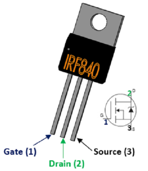
IRF840 pinout
irf840 Picture
| Pin | Symbol | Description |
|---|---|---|
| 1 | Gate | Connect to the control signal port and control the switch through the pin |
| 2 | Drain | Current flows into the port, connect to the power supply |
| 3 | Source | Current outflow port, ground |
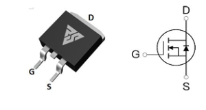
IRF840 Equivalent

irf840 Picture
IRF840 is a high-performance N-channel MOSFET transistor often used in electronic circuit design, widely used in switching power supply circuit, inverter circuit design. Its specific parameters are as follows: the maximum voltage value is 500V, which can meet the requirements of most circuits for voltage; The maximum acceptable current of 8A(with the increase of temperature this value will be reduced to 5.1A) is enough to meet the requirements of most circuits; Continuous high-power work will cause the transistor to heat up and reduce the power of the transistor, so we need to pay special attention to the solution of the heat dissipation problem (such as external heat sink or silicone grease); The on-resistance (Rds(on) of the IRF840 is only 0.7 ohms (rated to a maximum of 0.85 ohms), and the lower on-resistance can effectively reduce additional power losses and improve the efficiency of the circuit. The threshold voltage of IRF840 is 2V~4V, we can easily drive this transistor; And the switching time is only about 400ns, which can be used for high-frequency switching circuits. The package is in the form of TO-220, which has the advantage of easy heat dissipation and easy installation, and the disadvantage is that it takes up relatively large space.
IRF840 Replaceable Chip Table
| Name | Type | Vdss | Vgs | Id | Pd | Package |
|---|---|---|---|---|---|---|
| STW14NK50Z | N-MOSFET | 500V | 3V | 14A | 150W | TO-247-3 |
| RS18N50S | N-MOSFET | 500V | 4V | 18A | 140W | TO-263 |
| SIHG20N50C-JSM | N-MOSFET | 500V | 4V | 18A | 160W | TO-247 |
| VBM15R08 | N-MOSFET | 500V | 2V | 8A | 170W | ITO-220AB-3 |
| SPW16N50C3 | N-MOSFET | 500V | 3V | 16A | 160W | TO-247-3 |

STW14NK50Z Picture
RS18N50S Picture

SIHG20N50C-JSM Picture
VBM15R08 Picture

SPW16N50C3 Picture
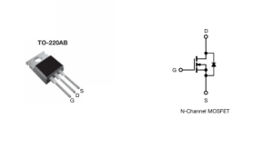
IRF840 Circuit Diagram
The irf840 is an N-channel type MOS field effect tube using a TO-220 package. The main features are low gate charge, low feedback capacitance, and very fast switching, so it is used as a switching tube in most cases, such as high-efficiency DC-DC (where different DC voltages can be output by switching at different frequencies).
irf840 maximum withstand voltage of 500V, in the series belongs to the highest withstand voltage value of a; large leakage current of 1mA; on-resistance of 0.85Ω (the smaller the on-resistance, indicating that the lower the static power consumption), the on-resistance is the largest in this series, because the irf840 positioning is to be a large withstand voltage and power, so the internal structure of a thicker, on-resistance will be large; Operating temperature range: -55 ℃ ~ +150 ℃; alternative products are: FTK480, KF12N50, IRF740, BSS138, etc. (choose a replacement material to consider the alternative components). Range: -55℃~+150℃; Alternative products are: FTK480, KF12N50, IRF740, BSS138, etc. (When choosing the alternative material, we should consider the voltage withstand value of the alternative components and the maximum current that supports the flow through).
How to drive a mos tube:

irf840 driver circuit diagram
Driving the irf840 requires a large enough transient current, and in addition to direct drive, the more common drive method is push-pull output (totem pole drive). R1 in the figure is the simulated load (can be led, fan, motor and other devices). Since the general microcontroller may not be able to output the current to meet the MOS drive, so we use a PNP and NPN emitter connected (common emitter amplifier circuit), the purpose is to amplify the MOS tube gate drive current.
More Like This
~~3.jpg "IRFU9024NPBF")
IRFU9024NPBF
Rochester Electronics, LLC

FDG6335N
Rochester Electronics, LLC

MMBFJ201
Rochester Electronics, LLC

IRF3205PBF
Rochester Electronics, LLC

IRFP1405PBF
Rochester Electronics, LLC

IRF3205ZSTRLPBF
Rochester Electronics, LLC

IRFP4229PBF
Rochester Electronics, LLC

IRFB7437PBF
Rochester Electronics, LLC
.jpg "IRLR9343TRPBF")
IRLR9343TRPBF
Rochester Electronics, LLC
IRFP4468PBF
Rochester Electronics, LLC
IRF640NSTRLPBF
Rochester Electronics, LLC

FDS6375
Rochester Electronics, LLC
Also Add to Cart

FDC604P
Rochester Electronics, LLC
FDS3572
onsemi,Rochester Electronics, LLC
.JPG "FDMC5614P")
FDMC5614P
onsemi

FDN86246
onsemi

2SK1317-E
Renesas Electronics America Inc

FDD16AN08A0
onsemi,Rochester Electronics, LLC

SIR826DP-T1-GE3
Vishay Siliconix
FDMC2523P
Rochester Electronics, LLC
IRFS4615TRLPBF
Infineon Technologies

2SK3541T2L
Rohm Semiconductor

FDMS86182
onsemi

AO4354
Alpha & Omega Semiconductor Inc.
IRFU9024NPBF
Rochester Electronics, LLC
FDG6335N
Rochester Electronics, LLC
MMBFJ201
Rochester Electronics, LLC
IRF3205PBF
Rochester Electronics, LLC
IRFP1405PBF
Rochester Electronics, LLC
IRF3205ZSTRLPBF
Rochester Electronics, LLC
IRFP4229PBF
Rochester Electronics, LLC
IRFB7437PBF
Rochester Electronics, LLC
IRLR9343TRPBF
Rochester Electronics, LLC
IRFP4468PBF
Rochester Electronics, LLC