
IRF540 | Datasheet, Pinout, Equivalent, Amplifier Circuit STMicroelectronics
- FET Type: N-Channel
- Drainto Source Voltage(Vdss): 100 V
- Current-Continuous Drain(Id)@25°C: 22A (Tc)
- Package: TO-220


FREE delivery for orders over HK$250.00

Quick response, quick quotaton

Flash shipment,no worries after sales

Original channel,guarantee of the authentic products
IRF series MOSFET IRF540, IRF740, IRFP450
IRF540 Equivalent

IRF540 Picture
IRF540 is an electronic engineer in the circuit design of a more commonly used N-channel enhancement MOSFET tube, with TO-22OAB this kind of relatively easy to dissipate the heat of the package, and the price is very cheap; the maximum branch of 33A current (under normal operating conditions, the temperature of the typical 25 degrees Celsius) continues to flow through, high current means that the maximum withstand the voltage is relatively large (through the datasheet can see the maximum withstand voltage of 100V), and the transistor also has a maximum power of 130W, is very suitable for high-power circuits or audio amplifiers; Rds is only 40 milliohms. Manual can see the maximum withstand voltage of 100V), and the transistor also has a maximum power of 130W, very suitable for high-power circuits or audio amplifiers; Rds is only 40 mOhm, components in the state of on-state loss of energy will be relatively small compared to other ones; irf540 also has a very good performance is to support fast switching, coupled with excellent anti-voltage Another good performance of irf540 is to support fast switching, coupled with excellent resistance to voltage, so that it can be used in high-voltage load switching circuits; in practice, the transistor is mainly used for voltage inverters, DCDC circuits, and high-speed switching circuits.
irf540 Replaceable Chip Table
| Name | Type | Vdss | Vgs | Pd | Package |
|---|---|---|---|---|---|
| SQD40P10-40L_GE3 | N-MOSFET | 100V | 2.5V | 136W | TO-252(DPAK) |
| OSD50N10G | N-MOSFET | 100V | 1.8V (typical value) | 135W | TO-252 |
| CMD40N20 | N-MOSFET | 200V | 3V | 135W | TO-252 |
| IPD110N12N3 | N-MOSFET | 120V | 4V | 136W | TO-252-3 |
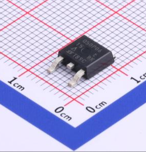
| AGM15T16D | N-MOSFET | 150V | 3.2V | 139W | TO-252 |

SQD40P10-40L_GE3 Picture

OSD50N10G Picture

CMD40N20 Picture
IPD110N12N3 Picture
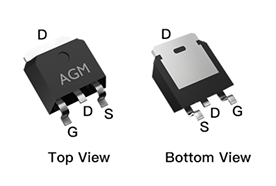
AGM15T16D Picture
IRF540 Circuit Diagram

irf540 Picture
IRF540 is a commonly used N-channel enhanced MOSFT, mainly used in high-power electrical drivers, switching power supplies, inverters and other electronic circuits. Because of its high current and voltage tolerance, it is one of the first choice objects in many power electronic circuit designs. Next, we will introduce the detailed parameters of the IRF540 and a typical application circuit diagram.
IRF540 Basic parameters:
Type: N channel MOSFET;
The maximum tolerable voltage is (VDS) : 100V;
The maximum current is (ID) : 33A;
The on-resistance is (RDS(on)) : 0.044 ohms;
The driving voltage is (VGS(th)) : 2~4V;
Package: TO-220AB-3
IRF540 Application Circuit Design:

irf540 application design drawing
This design is to use IRF540 to drive a high-power relay design, the circuit is mainly composed of a triode 2N3904 and relay and IRF540; First of all, the leftmost nmos driver circuit composed of 2N3904 is used to amplify the output of MCU to drive the IRF540 in the back. When MCU gives a high voltage level, Q1 conducts 24V through the two resistors R2 and R3 to divide the voltage to Q1 so that there is enough voltage to drive IRF540. When the IRF540 is turned on, 24V directly supplies power to the relay, and the relay coil is drawn and turned from normally open to normally closed. The function of D1 is to protect the circuit from burning out due to connection to the reverse power supply.
More Like This
~~3.jpg "IRFU9024NPBF")
IRFU9024NPBF
International Rectifier

FDG6335N
onsemi

MMBFJ201
onsemi

IRF3205PBF
International Rectifier

IRFP1405PBF
International Rectifier

IRF3205ZSTRLPBF
International Rectifier

IRFP4229PBF
International Rectifier

IRFB7437PBF
International Rectifier
.jpg "IRLR9343TRPBF")
IRLR9343TRPBF
International Rectifier
IRFP4468PBF
International Rectifier
IRF640NSTRLPBF
International Rectifier

FDS6375
National Semiconductor
Also Add to Cart
;;2.jpg "STD14NM50N")
STD14NM50N
STMicroelectronics
IRF640NSTRLPBF
International Rectifier

IRFB3607PBF
Infineon Technologies

AO3400A
Alpha & Omega Semiconductor Inc.

IRFH8318TRPBF
Infineon Technologies

FQA90N15
Fairchild Semiconductor

CSD19537Q3
Texas Instruments
IRF7240TRPBF
Infineon Technologies

IRFTS8342TRPBF
Infineon Technologies

SI2323DDS-T1-GE3
Vishay Siliconix
IRF4905PBF
Infineon Technologies

FQA70N15
Fairchild Semiconductor
Related Products
IRFU9024NPBF
International Rectifier
FDG6335N
onsemi
MMBFJ201
onsemi
IRF3205PBF
International Rectifier
IRFP1405PBF
International Rectifier
IRF3205ZSTRLPBF
International Rectifier
IRFP4229PBF
International Rectifier
IRFB7437PBF
International Rectifier
IRLR9343TRPBF
International Rectifier
IRFP4468PBF
International Rectifier
IRF640NSTRLPBF
International Rectifier
FDS6375
National Semiconductor
IRFB4332PBF
International Rectifier

IRFP3306PBF
International Rectifier

NVTFS5811NLTAG
onsemi
NVTFS4823NTWG
onsemi

NVD5117PLT4G
onsemi
IRF200S234
Infineon Technologies
.jpg "IRF840PBF")
IRF840PBF
Infineon Technologies

AO4407
Alpha & Omega Semiconductor Inc.
2SK3377-Z-E1-AZ
Renesas Electronics America Inc

NVD5867NLT4G
onsemi

NVMFS5A160PLZWFT1G
onsemi

FDWS9510L-F085
onsemi
FDWS9509L-F085
onsemi
NVTFS5826NLWFTAG
onsemi

AON7401L
Alpha & Omega Semiconductor Inc.
AO4407AL
Alpha & Omega Semiconductor Inc.
AO3407
Alpha & Omega Semiconductor Inc.

CPH3461-TL-W
onsemi
Please send RFQ , we will respond immediately.
