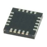
HMC539ALP3E Datasheet, Price, PDF
- Attenuation Value: 8dB
- Frequency Range: 0 Hz ~ 4 GHz
- Impedance: -
- Package: 16-VFQFN Exposed Pad

FREE delivery for orders over HK$250.00

Quick response, quick quotaton

Flash shipment,no worries after sales

Original channel,guarantee of the authentic products
hmc539alp3e
The HMC539ALP3E, made by Analog Devices (ADI), is a top-notch digital attenuator that’s perfect when you need precise control over RF and microwave signals. It covers a broad frequency range from DC all the way up to 4 GHz, so it’s great for a variety of applications like wireless communications, radar, or testing gear.
One of its standout features is the super-fine 0.5 dB steps, giving you total control up to 15.5 dB attenuation. Plus, at 2 GHz, you’re only losing about 1.2 dB in insertion loss, which means your signal stays strong and clear. It’s also highly linear, so it handles demanding signals without distortion.
Switching between attenuation settings is lightning-fast, perfect if you’re working with automatic gain control (AGC) systems. The chip itself is tiny—just 3×3 mm, in an easy-to-solder QFN package. And since it uses standard TTL/CMOS logic, hooking it up to your digital circuits is a breeze.
hmc539alp3e pinout
| Pin Number | Pin Name | Function Description |
|---|---|---|
| 1 | RF1 | RF Port 1 (Input/Output, bidirectional) |
| 2, 5, 8 | GND | Ground pins; require low impedance connections |
| 3 | Vdd | Positive power supply (typical voltage +5V) |
| 4 | P/S | Parallel/Serial mode select; controls interface mode |
| 6 | LE | Latch enable; controls input data latching |
| 7 | CLK | Clock input pin in serial mode |
| 9 | SERIN | Serial data input |
| 10 | RF2 | RF Port 2 (Input/Output, bidirectional) |
| 11 | VEE | Negative power supply (typical voltage -5V) |
| 12 | ACGND | Analog control ground; requires proper grounding |
| Exposed Pad | EP (Exposed Pad) | Bottom thermal pad; grounded for heat dissipation |
When you’re working with the HMC539ALP3E, there are a few practical things to keep in mind to make sure it performs reliably. First off, always ensure your power rails (+5V for Vdd and -5V for VEE) are clean and stable. Using some bypass capacitors can really help reduce any noise from the supply.
Next, pay attention to your RF ports—RF1 and RF2—since they’re designed for a 50Ω impedance. Getting your impedance matching right is crucial to avoid signal reflections and losses.
The P/S pin lets you choose between parallel or serial control mode, so double-check that you’ve got it set correctly. Also, grounding is key: connect GND and ACGND pins firmly to a low-resistance ground plane, and don’t forget the exposed pad underneath—it needs a good connection to ground to keep things cool and stable.
Finally, watch your digital control signals (like CLK, LE, and SERIN). Keep them within TTL/CMOS levels, avoiding overshoot to protect the chip and ensure consistent performance.
hmc539alp3e equivalent
| Parameter | HMC539ALP3E | HMC470ALP3E | HMC540LP3E | HMC311LP3E |
|---|---|---|---|---|
| Number of Bits | 5 bits | 5 bits | 4 bits | 5 bits |
| Minimum Step | 0.25 dB | 1 dB | 1 dB | 1 dB |
| Maximum Attenuation | 7.75 dB | 31 dB | 15 dB | 31 dB |
| Frequency Range | DC – 4 GHz | DC – 3 GHz | DC – 5.5 GHz | DC – 4 GHz |
| Control Type | Positive Logic Control | Positive Logic Control | Positive Logic Control | Positive Logic Control |
| Package Type | 16-QFN (LP3) | 16-QFN (LP3) | 16-QFN (LP3) | 16-QFN (LP3) |
| Operating Temperature | -40°C to +85°C | -40°C to +85°C | -40°C to +85°C | -40°C to +85°C |
| Supplier | Analog Devices | Analog Devices | Analog Devices | Analog Devices |
| RoHS Compliant | Yes | Yes | Yes | Yes |
If you’re thinking of swapping out the HMC539ALP3E, here are some solid options: The HMC470ALP3E works great if you need more attenuation (up to 31 dB), though keep in mind it steps in 1 dB increments, not 0.25 dB like your original. For broader frequency coverage up to 5.5 GHz, the HMC540LP3E is ideal. And if your setup runs up to 4 GHz needing decent attenuation, the HMC311LP3E can fit the bill. Just double-check the pin layouts and control logic to avoid modifying your PCB, and don’t overlook thermal and power handling to ensure reliable performance.
hmc539alp3e rf switch circuit
hmc539alp3e RF Step Attenuator Circuit

Let me briefly walk you through this RF circuit using the HMC539ALP3E. The RF signal goes into RF1, passes through coupling capacitors (C1 and C2) for DC blocking and keeping the impedance at 50Ω, and comes out at RF2. Vdd is your power pin, stabilized by capacitor C3 to cut noise. The ACG pins (ACG1–ACG5) connect to ground via capacitor C4, reducing interference. Digital control pins (V1–V5) link through resistors (R1–R5) to external logic for setting attenuation levels. Remember, this circuit controls RF power levels—it’s not an RF switch. For switching signals, consider something like the HMC349ALP3E.
hmc539alp3e switch frequency range
hmc539alp3e smd footprint
If you’re working with Analog Devices’ HMC539ALP3E digital attenuator, let me quickly cover its packaging details. It’s a compact, surface-mount 16-pin LFCSP measuring just 3 mm by 3 mm. Pin spacing is tight at 0.5 mm, so your PCB pads should be about 0.25 mm by 0.5 mm for reliable soldering. Don’t forget about the exposed pad underneath (1.65 mm square)—make sure it connects directly to your PCB ground for better thermal and electrical performance. Check out Analog Devices’ datasheet to see exact pad layouts—this will ensure your PCB design turns out perfectly.


