
ESP-WROOM-32 pinout & datasheet | pdf
- RF Family: WiFi
- Protocol: 802.11b/g/n/d/e/i
- Serial Interfaces: I²C, I²S, SPI, UART
- Package: Bulk


FREE delivery for orders over HK$250.00

Quick response, quick quotaton

Flash shipment,no worries after sales

Original channel,guarantee of the authentic products
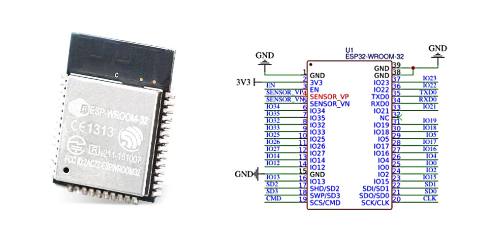
ESP-WROOM-32 is a handy Wi-Fi and Bluetooth combo module developed by Espressif, which has gained huge popularity among electronics enthusiasts in recent years. To put it simply, it’s like a small yet powerful “brain” for IoT projects. You just power it up, and it quickly connects to Wi-Fi or interacts with devices like phones and computers via Bluetooth.
ESP-WROOM-32 pinout
| Pin No. | Name | Function Description |
|---|---|---|
| 1 | GND | Ground pin |
| 2 | 3V3 | 3.3V Power Supply Input |
| 3 | EN | Module Enable Pin |
| 4 | SENSOR_VP | GPIO36, ADC Input (Input only) |
| 5 | SENSOR_VN | GPIO39, ADC Input (Input only) |
| 6 | IO34 | GPIO34, ADC Input (Input only) |
| 7 | IO35 | GPIO35, ADC Input (Input only) |
| 8 | IO32 | GPIO32, ADC, DAC, GPIO |
| 9 | IO33 | GPIO33, ADC, DAC, GPIO |
| 10 | IO25 | GPIO25, ADC, DAC, GPIO |
| 11 | IO26 | GPIO26, ADC, DAC, GPIO |
| 12 | IO27 | GPIO27, ADC, DAC, GPIO |
| 13 | IO14 | GPIO14, ADC, GPIO, PWM |
| 14 | IO12 | GPIO12, ADC, GPIO, PWM |
| 15 | GND | Ground pin |
| 16 | IO13 | GPIO13, ADC, GPIO, PWM |
| 17 | SD2/IO9 | GPIO9, SPI/SD Interface |
| 18 | SD3/IO10 | GPIO10, SPI/SD Interface |
| 19 | CMD/IO11 | GPIO11, SPI/SD Interface |
| 20 | CLK/IO6 | GPIO6, SPI/SD Interface |
| 21 | SD0/IO7 | GPIO7, SPI/SD Interface |
| 22 | SD1/IO8 | GPIO8, SPI/SD Interface |
| 23 | IO15 | GPIO15, ADC, GPIO, PWM |
| 24 | IO2 | GPIO2, ADC, GPIO, PWM |
| 25 | IO0 | GPIO0, Boot mode (Firmware download mode pin) |
| 26 | IO4 | GPIO4, ADC, GPIO, PWM |
| 27 | IO16 | GPIO16, ADC, GPIO, PWM |
| 28 | IO17 | GPIO17, ADC, GPIO, PWM |
| 29 | IO5 | GPIO5, ADC, GPIO, PWM |
| 30 | IO18 | GPIO18, ADC, GPIO, PWM |
| 31 | IO19 | GPIO19, ADC, GPIO, PWM |
| 32 | GND | Ground pin |
| 33 | IO21 | GPIO21, ADC, GPIO, PWM |
| 34 | RXD0/IO3 | GPIO3, UART0 RX (Receive) Pin |
| 35 | TXD0/IO1 | GPIO1, UART0 TX (Transmit) Pin |
| 36 | IO22 | GPIO22, ADC, GPIO, PWM |
| 37 | IO23 | GPIO23, ADC, GPIO, PWM |
| 38 | GND | Ground pin |
-
Most GPIO pins on ESP-WROOM-32 can be configured as digital input/output, ADC input, PWM output, as well as special interfaces such as UART, SPI, and I²C.
-
SENSOR_VP, SENSOR_VN, IO34, and IO35 are input-only GPIO pins.
-
Special attention is needed for GPIO0, GPIO2, and EN pins regarding their states during boot-up and firmware flashing.
-
ESP-WROOM-32 operates strictly on 3.3V. Supplying higher voltage may damage the module.
ESP-WROOM-32 power consumption
ESP-WROOM-32 has excellent power consumption performance, particularly in deep sleep mode, making it ideal for battery-powered applications.
| Operating Mode | Typical Current Consumption |
|---|---|
| Wi-Fi Transmission (Transmit mode) | 120 ~ 240 mA (depending on transmit power) |
| Wi-Fi Data Reception (Receive mode) | 95 ~ 110 mA |
| Bluetooth Transmission (BLE broadcast) | 80 ~ 130 mA |
| Idle mode (RF turned off) | 20 ~ 40 mA |
| Light Sleep mode | 0.8 ~ 1.5 mA |
| Deep Sleep mode | 10 ~ 150 µA (depending on RTC state) |
ESP-WROOM-32 equivalent module
| Module | Flash / PSRAM | Antenna Type | Package Size (mm) | Notes |
|---|---|---|---|---|
| ESP-WROOM-32 | 4MB / None | PCB Trace | 18 × 25.5 × 3.1 | Original module with integrated PCB antenna. |
| ESP32-WROOM-32D | 4MB / None | PCB Trace | 18 × 25.5 × 3.1 | Improved RF performance; same footprint as ESP-WROOM-32. |
| ESP32-WROOM-32U | 4MB / None | U.FL Connector | 18 × 19.2 × 3.2 | Similar to 32D but with external antenna support via U.FL connector. |
| ESP32-WROOM-32E | 4MB / None | PCB Trace | 18 × 25.5 × 3.1 | Updated version with improved manufacturing process and reliability. |
| ESP32-WROVER-B | 4MB / 8MB | PCB Trace | 18 × 31.4 × 3.3 | Includes 8MB PSRAM; suitable for applications requiring more memory. |
| ESP32-WROVER-IB | 4MB / 8MB | U.FL Connector | 18 × 31.4 × 3.3 | WROVER-B variant with external antenna support via U.FL connector. |
ESP-WROOM-32 wiring circuit example

Key Connections:
-
Power Supply:
A regulator (such as AMS1117-3.3) is used to convert a 5V input to 3.3V required by the ESP32 module. -
Enable Pin (EN):
Connected through a pull-up resistor to 3.3V to ensure the module starts correctly. -
Boot Pin (IO0):
Usually controlled by a button; used to enter firmware download mode. -
Reset Pin (EN):
Connected to a reset button, allowing manual restart of the module. -
UART Communication (TXD0/RXD0):
Connected to a USB-to-Serial converter chip (like CP2102) for programming and debugging communication. -
USB Interface:
Provides power and serial communication capability.
ESP-WROOM-32 arduino code example
Here’s a quick example code for testing the Wi-Fi connection of the ESP-WROOM-32 module using the Arduino IDE.
#include <WiFi.h>
const char* ssid = “yourSSID”;
const char* password = “yourPASSWORD”;
void setup() {
Serial.begin(115200);
delay(1000);
Serial.println(“Connecting to WiFi…”);
WiFi.begin(ssid, password);
while (WiFi.status() != WL_CONNECTED) {
delay(500);
Serial.print(“.”);
}
Serial.println(“”);
Serial.println(“WiFi connected!”);
Serial.print(“IP address: “);
Serial.println(WiFi.localIP());
}
void loop() {
}
More Like This

113990051
Seeed Technology Co., Ltd

LXRFZZUCCA-037
Murata Electronics

B82450A7204E000
EPCOS - TDK Electronics
B82450A1855E001
EPCOS - TDK Electronics

LXRFZZUCCA-036
Murata Electronics

B82450A4904A000
EPCOS - TDK Electronics

ANFCA-5035-A01-IPEX
Abracon LLC

2093610120030
HARTING

2093610220010
HARTING

B82450A7004E000
EPCOS - TDK Electronics

ANFCA-2525-A02
Abracon LLC

ANFCA-4030-A02
Abracon LLC
Also Add to Cart

CC110LRGPR
Texas Instruments
300
RevX Systems Corp.

SIM-N2-2FF3FF4FF
Hologram, Inc.

DA14585-00000AT2
Dialog Semiconductor GmbH
BCM43684B1KRFBG
Broadcom Limited

HMC525LC4
Analog Devices Inc.

L80RE-M37
Quectel

HMC284MS8GE
Analog Devices Inc.

1663.000.00
FEIG Electronic
ACFM-2247-SG1
Broadcom Limited

HMC253LC4
Analog Devices Inc.

CC2640F128RGZR
Texas Instruments
Related Products
113990051
Seeed Technology Co., Ltd
LXRFZZUCCA-037
Murata Electronics
B82450A7204E000
EPCOS - TDK Electronics
B82450A1855E001
EPCOS - TDK Electronics
LXRFZZUCCA-036
Murata Electronics
B82450A4904A000
EPCOS - TDK Electronics
ANFCA-5035-A01-IPEX
Abracon LLC
2093610120030
HARTING
2093610220010
HARTING
B82450A7004E000
EPCOS - TDK Electronics
ANFCA-2525-A02
Abracon LLC
ANFCA-4030-A02
Abracon LLC

ANFCA-4040-A02
Abracon LLC

ANFCA-4535-A01
Abracon LLC

ANFCA-5035-A01
Abracon LLC

ANFCA-5040-A02
Abracon LLC

ANFCA-1510-A02
Abracon LLC

ANFCA-2515-A02
Abracon LLC

ANFCA-3225-A02
Abracon LLC

20932010102
HARTING

20932010302
HARTING

20932010103
HARTING

20932010303
HARTING
CWB37CO
TE Connectivity Laird
CWB30CO
TE Connectivity Laird
CWB1443CO
TE Connectivity Laird
CW50CO
TE Connectivity Laird
CW4405CRO
TE Connectivity Laird
CW42CO
TE Connectivity Laird
CW37CO
TE Connectivity Laird
Please send RFQ , we will respond immediately.
