BSS84LT1G | Datasheet, Price, PDF onsemi
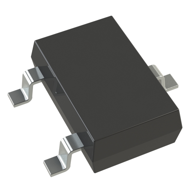
- FET Type: P-Channel
- Drainto Source Voltage(Vdss): 50 V
- Current-Continuous Drain(Id)@25°C: 130mA (Ta)
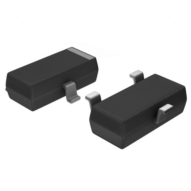
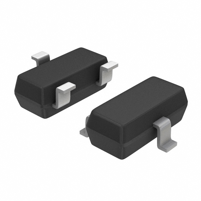
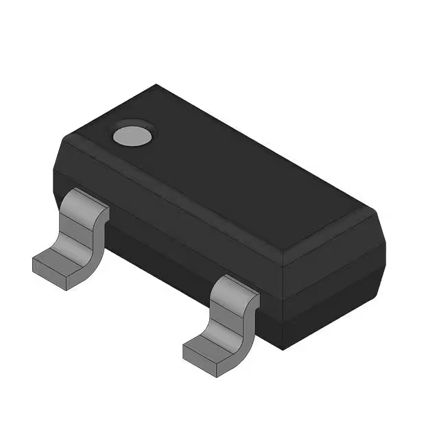
- Package: SOT-23-3 (TO-236)

FREE delivery for orders over HK$250.00

Quick response, quick quotaton

Flash shipment,no worries after sales

Original channel,guarantee of the authentic products
bss84lt1g
The BSS84LT1G is a neat little P-channel MOSFET that’s perfect when you’re designing portable electronics or low-voltage control circuits. It’s compact, with a SOT-23 package, saving valuable PCB space. This MOSFET handles up to -50V on the drain-source and currents up to -130mA comfortably. It turns on easily with a logic-friendly threshold around -2.0V, meaning you can directly control it from microcontrollers or digital circuits.
Its low power loss (around 225mW) and quick switching capabilities make it ideal for battery-powered applications, logic-level interface conversion, and small current switching tasks. Whether you’re working on a portable gadget, managing power co
bss84lt1g pinout configuration
| Pin Number | Pin Name | Description |
|---|---|---|
| 1 | Gate (G) | Gate pin, controls MOSFET switching |
| 2 | Source (S) | Source pin, typically connected to higher potential node (for P-channel MOSFET, connected to positive voltage supply) |
| 3 | Drain (D) | Drain pin, connected to load terminal |
When using the BSS84LT1G MOSFET, keep in mind that the Gate pin is your control point—lowering the gate voltage below the threshold switches it on, while raising it above switches it off. Just be careful not to exceed the maximum rated gate voltage to prevent damaging it.
Since it’s a P-channel MOSFET, your Source pin usually connects to the higher voltage side, like your positive power rail. Double-check this connection to avoid mistakes.
The Drain pin connects directly to your load, with the other side of your load typically going to ground or a lower voltage level.
In your PCB layout, position this MOSFET close to both your load and the control signal. Shorter leads help reduce interference and parasitic inductance. Also, ensure the current and voltage across your MOSFET stay within its ratings to avoid overloading and potential damage.
bss84lt1g equivalent p-channel mosfet
| Parameter/Model | BSS84LT1G (Original) | BSS84 (onsemi) | BSS84-7-F (Diodes Inc.) | CJ2301 (CJ) | IRLML6402 (Infineon) |
|---|---|---|---|---|---|
| Package | SOT-23 | SOT-23 | SOT-23 | SOT-23 | SOT-23 |
| Max Drain-Source Voltage (VDS) | -50 V | -50 V | -50 V | -30 V | -20 V |
| Max Drain Current (ID) | -130 mA | -130 mA | -130 mA | -2.3 A | -3.7 A |
| RDS(on) | 10 Ω @ -5 V | 10 Ω @ -5 V | 10 Ω @ -5 V | 0.1 Ω @ -4.5 V | 0.055 Ω @ -4.5 V |
| Gate-Source Voltage (VGS) Range | ±20 V | ±20 V | ±20 V | ±20 V | ±20 V |
| Power Dissipation (PD) | 225 mW | 225 mW | 225 mW | 350 mW | 1.25 W |
| Logic Level Drive | Yes | Yes | Yes | Yes | Yes |
| Suitable Current Range | Low Current | Low Current | Low Current | Medium Current | Medium Current |
When picking an alternative MOSFET to the BSS84LT1G, first match the basics: voltage and current ratings. For instance, some options like CJ2301 or IRLML6402 might have lower maximum voltages, so double-check if your circuit really needs higher voltage handling.
Next, consider the MOSFET’s on-resistance (R_DS(on)). A lower on-resistance helps your circuit run cooler and more efficiently. If your design cares about efficiency, models like IRLML6402 could be a better fit.
All recommended substitutes come in a compact SOT-23 package, so swapping them onto your PCB is straightforward. They also work well with standard 3.3V or 5V logic signals, making integration easy.
Lastly, watch out for the device’s maximum power dissipation rating. Ensure your chosen replacement won’t overheat in your actual application, keeping things running smoothly and safely.

~~3.jpg)



.jpg)
.jpg)


;;3.jpg)


