When you’re picking an alternative microcontroller, keep these points in mind: if your original program needs more than 4KB memory, consider going with something like the AT89S52, STC89C51RC, or SST89E516RD2. For higher performance, STC and SST chips can run up to 40MHz. Remember, most replacements use the 8051 core, but you might have to tweak your code for special features. They all support ISP for easy programming, but double-check the protocols just to be safe. Generally speaking, AT89S52-24AU works great if you want minimal changes, while STC89C51RC or SST89E516RD2 offer extra capacity and speed.

AT89S51-24AU datasheet, price | pdf Atmel
Discover the AT89S51-24AU Reference Manual for comprehensive guidance and technical details. This essential pdf provides crucial information, ensuring you get the best value and performance for your projects. Check the price and enhance your understanding of this advanced component.
- CoreProcessor: 8051
- Core Size: 8-Bit
- Peripherals: WDT
- Package: 44-TQFP


FREE delivery for orders over HK$250.00

Quick response, quick quotaton

Flash shipment,no worries after sales

Original channel,guarantee of the authentic products
At89s51-24au
If you’re using the AT89S51-24AU microcontroller, here’s what you’ll appreciate: it’s a reliable 8-bit chip based on the classic 8051 core, running up to 24MHz—fast enough for most everyday tasks. You’ve got 4KB of rewritable Flash memory, perfect for quick updates or small-scale projects, along with 128 bytes of RAM for basic data handling. Its 32 flexible I/O pins and built-in UART make connecting sensors or PCs straightforward. Plus, two built-in timers help with tasks like PWM and timing. Just remember: keep the power stable at 5V (±10%), and pay extra attention to your crystal and reset circuits to avoid headaches later.
At89s51-24au Pinout

| Pin Number | Pin Name | Pin Function Description |
|---|---|---|
| 1 | P1.5 | General I/O, Port 1 bit 5 |
| 2 | P1.6 | General I/O, Port 1 bit 6 |
| 3 | P1.7 | General I/O, Port 1 bit 7 |
| 4 | RST | Reset Input, Active High |
| 5 | P3.0/RXD | General I/O, UART Receive Pin (RXD) |
| 6 | P3.1/TXD | General I/O, UART Transmit Pin (TXD) |
| 7 | P3.2/INT0 | General I/O, External Interrupt INT0 |
| 8 | P3.3/INT1 | General I/O, External Interrupt INT1 |
| 9 | P3.4/T0 | General I/O, Timer 0 Input (T0) |
| 10 | P3.5/T1 | General I/O, Timer 1 Input (T1) |
| 11 | P3.6/WR | General I/O, External RAM Write Strobe (WR) |
| 12 | P3.7/RD | General I/O, External RAM Read Strobe (RD) |
| 13 | XTAL2 | Crystal Oscillator Output |
| 14 | XTAL1 | Crystal Oscillator Input |
| 15 | GND | Ground |
| 16 | P2.0/A8 | General I/O, External Address Line A8 |
| 17 | P2.1/A9 | General I/O, External Address Line A9 |
| 18 | P2.2/A10 | General I/O, External Address Line A10 |
| 19 | P2.3/A11 | General I/O, External Address Line A11 |
| 20 | P2.4/A12 | General I/O, External Address Line A12 |
| 21 | P2.5/A13 | General I/O, External Address Line A13 |
| 22 | P2.6/A14 | General I/O, External Address Line A14 |
| 23 | P2.7/A15 | General I/O, External Address Line A15 |
| 24 | PSEN | Program Storage Enable, External ROM Read |
| 25 | ALE/PROG | Address Latch Enable / Flash Programming Pulse |
| 26 | EA/VPP | External Access Enable / Programming Voltage Input |
| 27 | P0.7/AD7 | General I/O, Data/Address Line AD7 |
| 28 | P0.6/AD6 | General I/O, Data/Address Line AD6 |
| 29 | P0.5/AD5 | General I/O, Data/Address Line AD5 |
| 30 | P0.4/AD4 | General I/O, Data/Address Line AD4 |
| 31 | P0.3/AD3 | General I/O, Data/Address Line AD3 |
| 32 | P0.2/AD2 | General I/O, Data/Address Line AD2 |
| 33 | P0.1/AD1 | General I/O, Data/Address Line AD1 |
| 34 | P0.0/AD0 | General I/O, Data/Address Line AD0 |
| 35 | VCC | Power Supply Voltage (+5V) |
| 36 | P1.0/T2 | General I/O, Timer 2 |
| 37 | P1.1/T2EX | General I/O, Timer 2 External Input |
| 38 | P1.2 | General I/O, Port 1 bit 2 |
| 39 | P1.3 | General I/O, Port 1 bit 3 |
| 40 | P1.4 | General I/O, Port 1 bit 4 |
When you’re hooking up this chip, remember these basics: pin 35 (VCC) needs a steady +5V supply, and pin 15 (GND) must be well-grounded. For your crystal, connect XTAL1 and XTAL2 with a crystal oscillator plus two 22pF capacitors—this gives you a stable clock. Don’t forget the reset pin (pin 4); connect it to VCC through a 10kΩ resistor, and maybe add a capacitor if you want automatic resets on startup. Port 0 might need pull-up resistors if you’re connecting external memory. Finally, tie EA (pin 26) to VCC for internal memory or ground for external. Keep your wiring neat to avoid glitches!
At89s51-24au Equivalent Microcontroller


| Parameter | AT89S51-24AU | AT89S52-24AU | STC89C51RC-40I-TQFP44 | SST89E516RD2-40-C-TQJE |
|---|---|---|---|---|
| Core Architecture | 8051 (8-bit) | 8051 (8-bit) | 8051 (8-bit) | 8051 (8-bit) |
| Clock Frequency | 24 MHz | 24 MHz | 40 MHz | 40 MHz |
| Flash Memory | 4 KB | 8 KB | 32 KB | 64 KB |
| RAM Capacity | 128 Bytes | 256 Bytes | 1280 Bytes | 1024 Bytes |
| I/O Pins | 32 | 32 | 32 | 32 |
| Operating Voltage | 4.0~5.5V | 4.0~5.5V | 4.0~5.5V | 4.0~5.5V |
| Communication Interface | UART, SPI | UART, SPI | UART, SPI | UART, SPI |
| Timers/Counters | 2 x 16-bit | 3 x 16-bit | 3 x 16-bit | 3 x 16-bit |
| Package | TQFP-44 | TQFP-44 | TQFP-44 | TQFP-44 |
| ISP Programming | Supported | Supported | Supported | Supported |
| Industrial Temperature Range | -40°C ~ +85°C | -40°C ~ +85°C | -40°C ~ +85°C | -40°C ~ +85°C |
At89s51-24au Minimum System Circuit
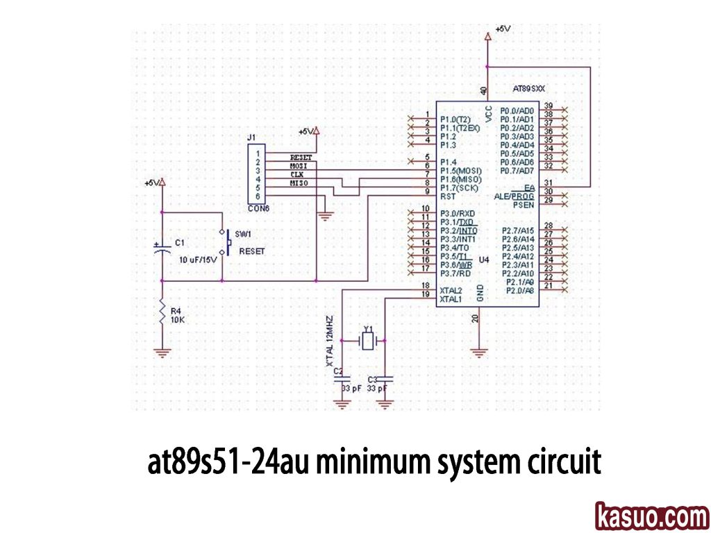
When you’re setting up this microcontroller, start with a stable +5V supply connected to pin 40 (VCC), and ground pin 20 (GND). Use a 12MHz crystal (Y1) with two 33pF capacitors at XTAL1 (pin 19) and XTAL2 (pin 18) for accurate timing. For resets, add a 10µF capacitor and a 10kΩ resistor with a reset button, giving you automatic and manual reset options. Include an ISP connector (CON6) for easy programming via pins P1.5, P1.6, and P1.7. Make sure your connections are neat—especially the crystal lines—and double-check resistor and capacitor values to ensure everything runs smoothly.
At89s51-24au Vs At89c51
| Parameter | AT89S51-24AU | AT89C51 |
|---|---|---|
| Architecture | 8-bit 8051 | 8-bit 8051 |
| Operating Voltage Range | 4.0 ~ 5.5 V | 4.0 ~ 5.5 V |
| Max Clock Frequency | 24 MHz | 24 MHz |
| Program Memory Type | Flash | Flash |
| Program Memory Capacity | 4 KB | 4 KB |
| RAM Capacity | 128 Bytes | 128 Bytes |
| Program Erase/Write Cycles | 1000 cycles (typical) | 1000 cycles (typical) |
| Package | TQFP-44 (SMD) | DIP-40, PLCC-44 (Through-hole) |
| I/O Pins | 32 General-purpose I/O | 32 General-purpose I/O |
| Timers/Counters | 2 | 2 |
| Serial Communication Interface | 1 UART | 1 UART |
| Interrupt Sources | 5 | 5 |
| Power-on Reset | Built-in power-on reset | No built-in power-on reset (External required) |
| ISP Programming | ISP Programming Not Supported | ISP Programming Not Supported |
| Operating Temperature | -40°C ~ +85°C (Industrial) | 0°C ~ +70°C (Commercial) |
If you’re thinking about replacing your AT89C51 with an AT89S51-24AU, here’s the deal: they’re pretty much identical in terms of performance and core features, but watch out for the packaging. The AT89S51-24AU comes in a compact TQFP-44 package, perfect if you’re tight on space, whereas the AT89C51 typically uses DIP-40 or PLCC-44, suited for traditional circuits. Also, the AT89S51 has a built-in power-on reset circuit—meaning less hassle for you—but you’ll need to tweak your design if you previously added your own reset circuitry. Lastly, just make sure your environment meets industrial temperature specs.
At89s51-24au Programming Using Isp
Here’s the deal with the AT89S51-24AU: it doesn’t directly support ISP (In-System Programming), so you can’t just program it right on the board. That’s because it lacks the internal hardware needed for ISP. You’ll have to burn your code externally using a dedicated programmer and then install the chip on your PCB afterward. But if easy online programming matters to you, consider upgrading to an ISP-compatible version like the AT89S52. This chip lets you program through a simple serial connection right on your board. Just make sure your ISP wiring matches the datasheet specs, and you’ll save lots of hassle!
At89s51-24au Keil Compiler Example
Let me quickly walk you through programming your AT89S51-24AU chip using Keil µVision. First, open Keil and create a new project (Project → New µVision Project). Select AT89S51 as your device. Then, add a new C file to write your code—like making LEDs blink or testing I/O pins. Next, set your crystal frequency (usually 12MHz), memory options, and select HEX as your output in “Options for Target.” Hit “Build,” and if everything goes smoothly, you’ll get your HEX file. Finally, upload this HEX file onto your chip using an external programmer (since AT89S51 doesn’t support ISP). Simple and quick!
At89s51-24au Fuse Bits Settings
If you’re working with the AT89S51-24AU, keep in mind it’s a classic 8051 microcontroller, so it doesn’t have fuse bits like AVR chips (such as ATmega or ATtiny). That means you won’t need to configure fuse bits for clock sources or startup conditions. Instead, all your settings come straight from your hardware connections—like choosing a crystal oscillator (usually 12MHz) or designing a simple RC reset circuit. However, it does have lock bits to protect your code from unauthorized reading, but these are totally different from fuse bits. So, setup here is straightforward—no complicated fuse settings required!
At89s51-24au Arduino Comparison
| Parameter or Feature | AT89S51-24AU | Arduino UNO (ATmega328P) |
|---|---|---|
| Architecture | 8051 (8-bit) | AVR (8-bit) |
| Clock Frequency | Up to 24 MHz (Typical 12 MHz) | 16 MHz (Typical) |
| Operating Voltage | 4.0 – 5.5V | 5V |
| Program Memory Type | Flash | Flash |
| Program Memory Capacity | 4KB | 32KB (0.5KB used by Bootloader) |
| RAM Capacity | 128 Bytes | 2KB |
| EEPROM (Non-volatile) | None | 1KB |
| Number of I/O Pins | 32 | 20 (14 Digital I/O, 6 Analog Input) |
| ADC (Analog-to-Digital Conversion) | No built-in ADC | Built-in 10-bit ADC, 6 channels |
| PWM Output | No dedicated PWM channels | 6 PWM channels |
| UART Interface | 1 UART | 1 UART |
| SPI/I²C Interface | No built-in hardware support | Built-in SPI, I²C interfaces |
| ISP Programming | Not Supported | Supported |
| Programming Method | External Programmer Required | USB to Serial (Built-in Bootloader) |
| Development Environment | Keil, Assembly, etc. | Arduino IDE (C/C++) |
| Community and Libraries | Limited | Extensive community and library support |
| Package Type | TQFP-44 SMD | DIP-28 or TQFP-32 |
When you’re picking between Arduino UNO and AT89S51-24AU, here’s how I’d break it down for you:
Arduino UNO is super beginner-friendly. It comes loaded with handy features like built-in ADC, PWM, SPI, and I²C, plus plenty of libraries to make your life easy. You don’t even need a special programmer—just plug it into your computer via USB and start coding right away. Perfect if you want quick results, flexibility, or you’re learning and experimenting.
On the other hand, the AT89S51-24AU is great if your project is simple, set-in-stone, and you’re looking to produce a lot at low cost. Just remember, you’ll need an external programmer, and expanding its features requires extra hardware.
At89s51-24au Microcontroller Projects
If you’re just starting with microcontrollers, the AT89S51-24AU is a great choice because it’s cheap, simple, and perfect for basic projects. Begin with something easy like an LED chaser, learning how to control outputs and create delays. After that, try a buzzer that you can trigger with buttons—good for practicing input detection. Moving forward, building a digital timer or a numeric countdown display with seven-segment LEDs will sharpen your understanding of dynamic displays and timing logic.
Once you’re comfortable, level up with temperature monitoring using a DS18B20 sensor, or make an electronic password lock with a keypad—ideal for learning communication protocols and input scanning.
When you’re ready for something practical, tackle projects like infrared remote control or a smart temperature-controlled fan. Just keep in mind, you’ll need external modules for things like ADC or PWM since the AT89S51 doesn’t have those built-in. Also, remember to have a programmer handy, as this chip doesn’t support ISP programming.
At89s51-24au Embedded System Applications
If you’re thinking about using the AT89S51-24AU microcontroller, it’s a classic and reliable choice, especially if you’re looking to keep costs down. It’s widely used in basic embedded projects because it’s easy to work with and pretty robust.
In industrial setups, you can use it for simple data collection, like measuring temperature or humidity, and controlling equipment through relays—think automated doors or motorized curtains. For consumer electronics, it’s ideal for designing user-friendly control panels in appliances such as microwaves or washing machines, or even fun educational toys and beginner-friendly learning kits.
You’ll also see it in security systems, like keypad-controlled electronic door locks, smoke detectors, and simple alarm setups. For automation and measurement devices, you can easily build instruments like basic timers, counters, or temperature controllers. And if you’re interested in communication, it handles basic infrared remote controls or serial connections like RS232 or RS485 smoothly. It’s perfect for practical, everyday applications.
More Like This

CBTL06GP213EE
NXP Semiconductors

MAX458EPL
Analog Devices / Maxim Integrated
ADG5412FBCPZ
Analog Devices
ADG5412BFBCPZ
Analog Devices
ADG854BCPZ
Analog Devices
DG187AA
Vishay / Siliconix

74LVC1G66GV
Nexperia
FSA2275A
onsemi
TC4066BP
Toshiba
74LVC2G66DP
Nexperia
74LVC1G66GW
Nexperia
ADG1414BCPZ
Analog Devices
Also Add to Cart

AM29F040B-90JF
Infineon Technologies

NCP1081DER2G
onsemi

AD9545BCPZ
Analog Devices Inc.

STM32L562VET6
STMicroelectronics

AD8676BRMZ-REEL
Analog Devices Inc.

STM32F100C6T7B
STMicroelectronics

SL18860DC
Skyworks Solutions Inc.

EVA-M8M-0-10
U-BLOX

MT29F1G08ABBFAH4-ITE:F
Micron Technology Inc.

AD5553CRMZ
Analog Devices Inc.

TP5551-TR
3PEAK

W25Q256JWPIQ
Winbond Electronics
Related Products
CBTL06GP213EE
NXP Semiconductors
MAX458EPL
Analog Devices / Maxim Integrated
ADG5412FBCPZ
Analog Devices
ADG5412BFBCPZ
Analog Devices
ADG854BCPZ
Analog Devices
DG187AA
Vishay / Siliconix
74LVC1G66GV
Nexperia
FSA2275A
onsemi
TC4066BP
Toshiba
74LVC2G66DP
Nexperia
74LVC1G66GW
Nexperia
ADG1414BCPZ
Analog Devices

MAX4649EKA
Analog Devices / Maxim Integrated
74HC1G66GW
Nexperia
74LVC4066PW
Nexperia
ADG702BRTZ
Analog Devices
ADG701BRTZ
Analog Devices

ADG1219BRJZ
Analog Devices

74HCT4066D
Nexperia
ADG819BRTZ
Analog Devices
HEF4066BT
Nexperia

74HC4066PW
Nexperia
ADG1436YCPZ
Analog Devices
74HC1G66GV
Nexperia
ADG802BRTZ
Analog Devices
CLC018AJVJQ
Texas Instruments
HEF4014BT
Nexperia

74HCT165D
Nexperia

MC14094BCP
onsemi
74HCT164D
Nexperia
Please send RFQ , we will respond immediately.

Please send RFQ , we will respond immediately.
Copyright © 2024 All Rights Reserved