
UA741CN データシート、回路、ピン図、PDF
- アンプタイプ: 汎用
- 回路数: 1
- 出力タイプ: -
- パッケージ: 8-DIP(0.300、7.62mm)


HK$250.00以上のご注文で送料無料

迅速な対応、迅速な見積もり

すぐに発送、アフターサービスも安心

オリジナルチャネル、本物の製品の保証
ua741cn
If you’re looking for a simple, reliable op-amp for general analog circuits, the UA741CN is a great choice. It’s designed for flexibility, working comfortably with dual power supplies from ±5V up to ±18V, though most commonly you’ll use ±15V. It’s got a high input impedance, so it won’t load down your input signal source, which helps maintain accuracy. Plus, it offers low input offset voltage (around 2mV), meaning your amplified signals stay precise.
Another nice feature is its built-in short-circuit protection—so you won’t easily damage it by accident. You also don’t need any extra parts for frequency compensation, as that’s already built in, making your design simpler. With a typical gain-bandwidth product of 1 MHz, it’s ideal for audio circuits or general-purpose amplification. The DIP-8 package is user-friendly and easy to solder, perfect for learning and prototyping. You’ll often find the UA741CN in filters, comparators, integrators, or just about any basic analog circuit project you tackle.
ua741cn pinout op amp
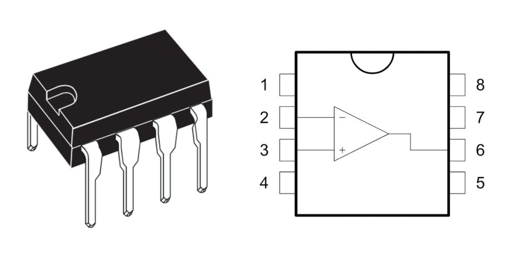
| ピン番号 | ピン名 | ピン機能の説明 |
|---|---|---|
| 1 | オフセットヌル | Offset voltage adjustment pin (usually left unconnected if not used) |
| 2 | Inverting Input (-IN) | Inverting input of the operational amplifier |
| 3 | Non-inverting Input (+IN) | Non-inverting input of the operational amplifier |
| 4 | V- (Negative Supply) | Negative power supply voltage (typically -12V to -15V) |
| 5 | オフセットヌル | Offset voltage adjustment pin (usually left unconnected if not used) |
| 6 | 出力 | Output signal terminal of the operational amplifier |
| 7 | V+ (Positive Supply) | Positive power supply voltage (typically +12V to +15V) |
| 8 | ノースカロライナ州 | No connection, not used |
When you’re wiring up the UA741CN op-amp, here are some simple tips to keep things running smoothly. First, use a dual power supply—around ±12V to ±15V is ideal—to make sure it works as expected. If you’re stuck with a single supply, you’ll need an extra biasing circuit or it won’t behave correctly.
Pins 1 and 5 are meant for offset voltage adjustments. Normally, you can leave these floating unless you’re building something that requires very precise accuracy; in that case, you’d add a potentiometer here.
Always make sure your input signals stay within your power supply range to avoid damaging the chip. Also, don’t short the output pin directly to power or ground, as this could burn it out. It’s safer to keep the output load resistance above 2kΩ, limiting the output current.
Finally, place a small ceramic capacitor (around 0.1µF) close to the power pins (4 and 7) to help filter noise and keep your op-amp stable.
ua741cn equivalent operational amplifier

| パラメータ/モデル | UA741CN | LM358N | TL071CP | TL081CP | NE5534N |
|---|---|---|---|---|---|
| Op Amp Type | General-purpose | General-purpose | Low-noise | Low-noise | High-performance audio |
| Operating Supply Voltage | ±5V ~ ±18V | 3V ~ 32V single supply or ±1.5V ~ ±16V dual supply | ±4.5V ~ ±18V | ±5V ~ ±18V | ±3V ~ ±20V |
| 利得帯域幅(GBW) | 1MHz | 0.7 MHz | 3MHz | 3MHz | 10MHz |
| スルーレート | 0.5 V/µs | 0.3 V/µs | 13 V/µs | 13 V/µs | 13 V/µs |
| 入力オフセット電圧 | ~2 mV | ~3 mV | ~3 mV | ~3 mV | ~0.5 mV |
| 入力インピーダンス | 中くらい | 中くらい | 高い | 高い | 高い |
| Output Short-circuit Protection | はい | はい | はい | はい | はい |
| Single/Dual Supply Compatibility | Mainly dual-supply | Single/Dual supply | Dual supply | Dual supply | Dual supply |
| パッケージ | DIP-8 | DIP-8 | DIP-8 | DIP-8 | DIP-8 |
When you’re looking for an alternative to the UA741CN op-amp, there’s a few important points to keep in mind. First, think about your power supply setup. If you’re using a single, lower-voltage power supply, the LM358N is a great budget-friendly choice. For general-purpose dual-supply setups similar to the 741, go with something like the TL071CP or TL081CP—they offer improved performance and speed. But if you’re building something like a high-quality audio circuit and need superior bandwidth and performance, the NE5534N will serve you even better.
Noise and precision matter, too. The UA741CN is solid for basic circuits, but for lower noise and better accuracy, the TL071, TL081, or NE5534 are all strong upgrades.
Also, make sure the replacement chip has a compatible pin layout, so you won’t need to redesign your PCB or wiring—saving you headaches later on. Choosing the right chip ensures your circuit will run reliably and efficiently without extra hassles.
ua741cn amplifier circuit schematic

In this circuit, the UA741CN op-amp plays a key role in amplifying the input signal. It receives signals through its differential inputs (+In and -In), suggesting this circuit might be a differential amplifier. The circuit also uses multiple NPN transistors (Q1 to Q24) to further amplify the signal, allowing the op-amp and transistors to work together for increased gain.
There are several resistors (R1 to R11) and capacitors (C0) in the circuit, which help set the gain, frequency response, and overall stability. These components ensure the circuit operates smoothly without oscillating or becoming unstable.
The power supply for this circuit is provided through the Vcc and Vee pins, giving the necessary positive and negative voltages for both the op-amp and transistors. The feedback network, made up of resistors and capacitors, controls the amplifier’s gain and keeps it stable, ensuring linear performance.
This setup is perfect for applications like audio amplification, signal processing, or sensor signal amplification, offering high gain and precision.
ua741cn inverting amplifier example
A basic inverting amplifier is a common setup using an op-amp, where the output signal is inverted compared to the input signal. In this configuration, the input signal is sent through a resistor to the inverting input (-) of the op-amp, while the non-inverting input (+) is typically grounded or connected to a reference voltage. A feedback resistor connects the output back to the inverting input, and by adjusting this resistor, you can control the gain of the amplifier.
For example, let’s say you’re using a UA741CN op-amp with an input resistor (Rin) of 10kΩ and a feedback resistor (Rf) of 100kΩ. Using the formula for gain, the gain would be -10, meaning the output signal will be 10 times the input signal, but inverted. So, if you input a 1V signal, the output would be -10V.
Inverting amplifiers are great for signal amplification, audio processing, and even basic mathematical operations like addition or subtraction. Just make sure to choose an appropriate gain, provide a stable power supply, and keep your input voltage within range to prevent damage.
ua741cn comparator circuit diagram

This circuit demonstrates how to set up the UA741CN op-amp as a comparator. Here’s how it works: the input signal (Vin) is connected to the non-inverting input (+) of the op-amp through a resistor (R1). The inverting input (-) gets a reference voltage (Vref), which in this case is set to 1V, defined by a resistor.
When the input signal (Vin) exceeds or falls below the reference voltage (Vref), the op-amp’s output (Vout) switches between high and low. If Vin is higher than Vref, the output is high (close to +Vcc), and if Vin is lower, the output is low (close to -Vee).
Two diodes (D1 and D2) are included to protect the op-amp from voltage spikes by limiting the input voltage range. The output is connected to a load resistor (Rl), which could control an indicator or other devices.
This comparator circuit is useful in applications like voltage monitoring, temperature sensing, and switch control where you need to detect when a signal crosses a threshold.
ua741cn audio amplifier project
If you’re looking to build a simple audio amplifier using the UA741CN op-amp, here’s how you can do it. First, you’ll need a few basic components: the UA741CN op-amp, resistors (R1 = 10kΩ, R2 = 100kΩ, R3 = 1kΩ), capacitors (C1 = 10µF for input coupling, C2 = 10µF for output coupling), and an 8Ω speaker. For the power supply, you can use either ±12V or a single 12V source.
The audio signal enters through C1 and goes to the non-inverting input of the op-amp. The op-amp amplifies the signal using the resistors R1 and R2 to set the gain (in this case, a gain of 11). The amplified signal passes through C2, which blocks any DC component and sends the audio signal to the speaker.
Make sure your power supply is within the op-amp’s working range, and adjust R1 and R2 to control the gain without overloading the output. If you need more power, consider using a dedicated audio power amplifier. This simple setup is perfect for small audio projects!
同様のもの

ISL99227FRZ-TR5784
ルネサス エレクトロニクス アメリカ株式会社

ISL99227HRZ-TR5784
ルネサス エレクトロニクス アメリカ株式会社

ISL99227BFRZ-TR5784
ルネサス エレクトロニクス アメリカ株式会社

ISL99360HRZ-TS2794
ルネサス エレクトロニクス アメリカ株式会社

ISL99227BFRZ-TR5783
ルネサス エレクトロニクス アメリカ株式会社

ISL99227BFRZ-TR5782
ルネサス エレクトロニクス アメリカ株式会社

ISL99227HRZ-TR5783
ルネサス エレクトロニクス アメリカ株式会社

ISL99227FRZ-TR5783
ルネサス エレクトロニクス アメリカ株式会社

ISL99227FRZ-TR5782
ルネサス エレクトロニクス アメリカ株式会社

ISL99227HRZ-TR5782
ルネサス エレクトロニクス アメリカ株式会社
WIZ750SR-DBL
WIZネット

W7500S2E-R1
WIZネット
カートに追加する

TLV9354IDR
テキサス・インスツルメンツ

NC7SZ125P5X
フェアチャイルドセミコンダクター

TPS54231D
テキサス・インスツルメンツ

TPS563210ADDFR
テキサス・インスツルメンツ

XC3S400-4FTG256I
AMD ザイリンクス

LM3481MMX/NOPB
テキサス・インスツルメンツ

TPS54521RHLR
テキサス・インスツルメンツ

SSM2166SZ
アナログ・デバイセズ株式会社

SST25VF040B-50-4I-S2AF
マイクロチップテクノロジー

AD9963BCPZ
アナログ・デバイセズ株式会社

INA121UA
バー・ブラウン

ADW71205YSTZ
アナログ・デバイセズ株式会社
関連製品
ISL99227FRZ-TR5784
ルネサス エレクトロニクス アメリカ株式会社
ISL99227HRZ-TR5784
ルネサス エレクトロニクス アメリカ株式会社
ISL99227BFRZ-TR5784
ルネサス エレクトロニクス アメリカ株式会社
ISL99360HRZ-TS2794
ルネサス エレクトロニクス アメリカ株式会社
ISL99227BFRZ-TR5783
ルネサス エレクトロニクス アメリカ株式会社
ISL99227BFRZ-TR5782
ルネサス エレクトロニクス アメリカ株式会社
ISL99227HRZ-TR5783
ルネサス エレクトロニクス アメリカ株式会社
ISL99227FRZ-TR5783
ルネサス エレクトロニクス アメリカ株式会社
ISL99227FRZ-TR5782
ルネサス エレクトロニクス アメリカ株式会社
ISL99227HRZ-TR5782
ルネサス エレクトロニクス アメリカ株式会社
WIZ750SR-DBL
WIZネット
W7500S2E-R1
WIZネット

W5500S2E-Z1
WIZネット

W5500S2E-S1
WIZネット

NM7010B+
WIZネット
APEHC-D40
アペイサーメモリアメリカ
APEHC-D30
アペイサーメモリアメリカ
APEHC-D10
アペイサーメモリアメリカ
APEFC-R50
アペイサーメモリアメリカ
APEFC-R40
アペイサーメモリアメリカ
APEFC-R30
アペイサーメモリアメリカ
APEFC-R10
アペイサーメモリアメリカ
APEFC-G50
アペイサーメモリアメリカ
APEFC-G40
アペイサーメモリアメリカ
APEFC-G30
アペイサーメモリアメリカ
APEFC-G10
アペイサーメモリアメリカ
APEFC-D50
アペイサーメモリアメリカ
MTIFM.R3-SP
マルチテックシステムズ株式会社
MTIFM.R3
マルチテックシステムズ株式会社
50040R-02
エシェロンコーポレーション
RFQ をお送りください。すぐに対応させていただきます。
