
LMC6482AIMX/NOPB データシート、価格、PDF ナショナルセミコンダクター
- アンプタイプ: CMOS
- 回路数: 2
- 出力タイプ: レールツーレール
- パッケージ: 8-SOIC(0.154、3.90mm幅)


HK$250.00以上のご注文で送料無料

迅速な対応、迅速な見積もり

すぐに発送、アフターサービスも安心

オリジナルチャネル、本物の製品の保証
lmc6482aimx/nopb
If you’re working on something that needs a reliable, rail-to-rail op amp, here’s a great choice. This little guy can run smoothly on anything from 3V up to 15V if you’re using a single supply, or ±1.5V to ±7.5V on a dual supply. What’s neat about it is its super-low input bias current—just around 20 femtoamps. That’s practically nothing, perfect if you’re dealing with sensitive measurements or need minimal leakage current.
Plus, it only draws about 1.1mA per channel, which means your battery-powered or portable designs stay efficient. With a slew rate around 1.3 V/μs and a gain bandwidth of 1.5 MHz, it’s great for most low- to mid-frequency tasks. Its true rail-to-rail capability lets you accurately measure signals right up to your power rails. Available in a compact SOIC-8 package, it’s easy to handle and great for tight spaces. Ideal for sensor circuits, medical devices, battery systems, and precision instruments.
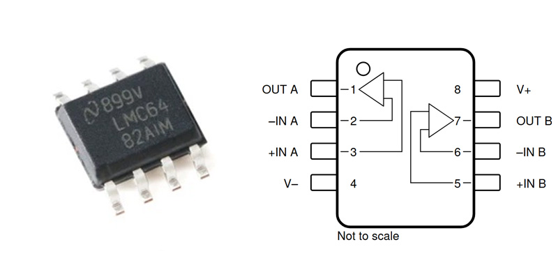
lmc6482aimx/nopb pinout
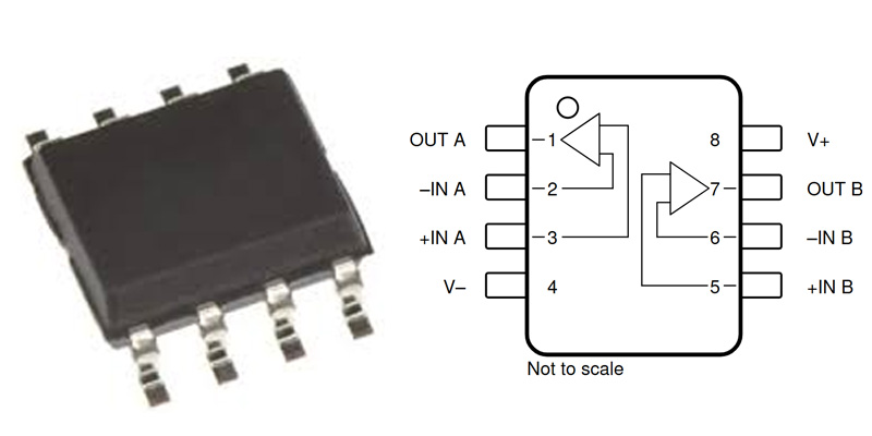
| ピン番号 | ピン名 | Pin Function Description |
|---|---|---|
| 1 | OUT A | Op Amp Channel A Output |
| 2 | -IN A | Op Amp Channel A Inverting Input |
| 3 | +Aで | Op Amp Channel A Non-inverting Input |
| 4 | V- | Negative Power Supply or Ground (Single Supply) |
| 5 | +Bで | Op Amp Channel B Non-inverting Input |
| 6 | -IN B | Op Amp Channel B Inverting Input |
| 7 | OUT B | Op Amp Channel B Output |
| 8 | V+ | Positive Power Supply |
When you’re hooking up this op amp, connect the V+ pin to your positive supply (3V–15V single or ±1.5V–±7.5V dual), and V- typically goes to ground or the negative rail. Never reverse these connections, or you might fry the chip. Keep your input signals within the supply voltage range—going beyond could damage your device, so protect those inputs from spikes. The output can swing nearly rail-to-rail, but don’t push the load beyond ±30mA, or you’ll risk losing accuracy and stability. For clean signals, route your PCB carefully, keeping input/output lines short, away from noisy power lines, and add a 0.1µF ceramic decoupling capacitor.
lmc6482aimx/nopb equivalent op amp


| Parameter/Model | LMC6482AIMX/NOPB | OPA2333AIDR | TLV2372IDR | OPA2188AIDR | LMC6062AIMX |
|---|---|---|---|---|---|
| パッケージタイプ | SOIC-8 | SOIC-8 | SOIC-8 | SOIC-8 | SOIC-8 |
| チャンネル | 2 | 2 | 2 | 2 | 2 |
| 利得帯域幅(GBW) | 1.5MHz | 350 kHz | 3MHz | 2MHz | 1.5MHz |
| スルーレート | 1.3 V/µs | 0.16 V/µs | 2.4 V/µs | 0.8 V/µs | 0.3 V/µs |
| Input Bias Current (Ib) | 20 fA | 0.1 pA | 1 pA | 200 fA | 20 fA |
| Operating Voltage Range (V) | 3 – 15 V | 1.8 – 5.5 V | 2.7 – 16 V | 2.7 – 36 V | 3 – 15 V |
| Rail-to-Rail Input | はい | はい | はい | はい | はい |
| Rail-to-Rail Output | はい | はい | はい | はい | いいえ |
| Typical Quiescent Current (per channel) | 0.55 mA | 0.017 mA | 0.55 mA | 0.45 mA | 0.4 mA |
| Recommended Applications | Ultra-low bias current, low-power sensor interfaces | Ultra-low power, zero drift battery-powered devices | High-speed audio and signal processing | Industrial control and precision measurement | Low-power, portable equipment |
When you’re replacing an op amp, first double-check your new chip’s voltage rating matches the original one—getting this wrong can cause trouble. If your circuit specifically needs rail-to-rail outputs, steer clear of options like LMC6062AIMX that don’t fully swing rail-to-rail. For battery-powered devices, pick an amp with low quiescent current, something like the OPA2333AIDR, to extend battery life. Always consider your actual application—choose OPA2188AIDR for precision measurements or TLV2372IDR for faster signal processing. And remember, always dive into the datasheet beforehand so you’re sure your new selection meets your specific design needs perfect
lmc6482aimx/nopb amplifier circuit example

Let’s quickly walk through how this circuit works, so you’ll get a clearer picture. Your input signal first comes into pin 2 of connector P2, and from there, it heads straight into the positive input of the LMC6482AIMX/NOPB op amp.
Now, the output from the op amp (pin 1) is looped back into the negative input through a feedback setup made of resistor R7 and capacitor C8, forming a closed-loop. There’s also resistor R5 placed at the output—this one’s important because it limits current flow, protecting both your op amp and whatever comes next (like the PA0 pin).
To keep the input signal clean, R6 and C6 make up a simple low-pass filter, cutting out any noisy high-frequency interference. The whole thing runs neatly on a single +5V supply, easily handling input and output signals within that voltage range.
You’ll often use this kind of circuit for impedance matching, buffering signals, and keeping your data accurate before feeding it into an ADC—perfect for stable and reliable signal processing.
lmc6482aimx/nopb rail-to-rail op amp
You might’ve heard about Rail-to-Rail Op Amps (RRO) before—these handy devices let your signals swing all the way up and down, nearly touching the power supply rails (like 0V and 5V). This means you can fully use the available voltage range without losing headroom.
Think of the “rails” as your upper and lower voltage limits. A rail-to-rail op amp is cleverly designed with complementary MOS transistors—both N-channel and P-channel types—so it automatically switches inputs when your signal approaches either rail. On the output side, there’s usually a push-pull stage, making sure your signal can reach right up to the power rails.
Why does this matter to you? Well, it simplifies your circuit designs—you only need a single power supply, no complicated dual supplies or offset voltages. Plus, by maximizing your voltage range, you’ll boost accuracy, reduce power consumption, and make your battery-powered devices last longer.
lmc6482aimx/nopb vs lm358
| パラメータ | LMC6482AIMX/NOPB | LM358 |
|---|---|---|
| チャンネル | 2 (Dual Channel) | 2 (Dual Channel) |
| Input/Output Type | Rail-to-Rail Input/Output (RRO) | Non Rail-to-Rail (Non-RRO) |
| 供給電圧範囲 | Single Supply 3–15 V or ±1.5–±7.5 V | Single Supply 3–32 V or ±1.5–±16 V |
| 利得帯域幅(GBW) | 1.5MHz | 0.7 MHz |
| スルーレート | 1.3 V/µs | 0.3 V/µs |
| Input Bias Current (Ib) | 20 fA (Ultra-low) | 20 nA (Relatively High) |
| 静止電流 | 0.55 mA/channel (Low Power) | 0.7 mA/channel (Moderate) |
| 入力電圧範囲 | Close to Supply Rails | Can only reach Negative Rail (Ground) |
| 出力電圧振幅 | Rail-to-Rail Output | Up to approx. V+ – 1.5 V (Non-RRO) |
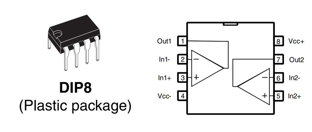
| パッケージタイプ | SOIC-8 (SMD) | Various, including SOIC-8, DIP-8 |
| Main Applications | Precision Measurement, Sensor Interfaces, Low-voltage Systems | General Amplification Circuits, Simple Applications |
If you’re thinking of swapping your LMC6482 for an LM358, there are a few important things to consider. First, the LM358 doesn’t support true rail-to-rail operation—it stops about 1.5V short of your positive rail, affecting both input and output voltage ranges. Also, its input bias current is much higher (around 20nA) compared to the super-low 20fA of the LMC6482. That difference matters a lot if you’re measuring tiny signals or using high-impedance sensors. Plus, the LM358 has lower bandwidth and slower slew rate, making it less suitable for fast or precise signals. But if you’re on a tight budget and precision isn’t critical, LM358 is a decent alternative.
lmc6482aimx/nopb dual op amp usage
If you’re working with dual-channel op amps, here’s where they’re really handy: precision amplifiers for sensor signals like temperature or pressure; buffering signals before feeding them into microcontroller ADCs; and creating low-power, battery-friendly circuits for portable devices like medical monitors or wireless sensors. They’re also perfect for building compact active filters—low-pass, high-pass, or band-pass—used in audio processing or noise reduction. When using these amps, keep power pins clean with a 0.1μF decoupling capacitor, keep input wires short to minimize noise, protect inputs from excessive voltages, and don’t exceed ±30mA on outputs to keep things stable and accurate.
lmc6482aimx/nopb low power opamp
If you’re looking for a low-power op amp, the LMC6482AIMX/NOPB could be perfect for your design. It uses just 0.55mA per channel, making it ideal for battery-powered devices. It also handles a wide voltage range (single 3-15V or dual ±1.5-±7.5V) while staying power-efficient. Thanks to its rail-to-rail capability, your signals can swing right up to the supply rails, maximizing your dynamic range. Its ultra-low input bias current (~20 fA) is great for sensitive, high-impedance sensors. Whether you’re building wireless sensors, portable medical gadgets, or precision measurement tools, this op amp keeps your design efficient, accurate, and battery-friendly.
lmc6482aimx/nopb signal conditioning circuit
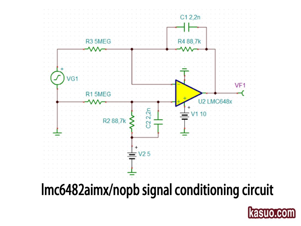
Here’s what’s happening in this circuit: Your input signal (VG1) first passes through resistors R1 and R3, creating a high-impedance path so it doesn’t load your source. The LMC6482 op amp is set up with negative feedback from R4 and C1, acting like an active filter—usually band-pass or high-pass, depending on your design. R2 and C2 give the positive input a stable DC offset and filter out unwanted noise, keeping your signal clean. Powered by a single 10V supply, this setup works perfectly for battery-powered devices. The output (VF1) is nicely filtered and amplified, ready for ADC sampling or precise measurement systems.
同様のもの

CBTL06GP213EE
NXPセミコンダクターズ

MAX458EPL
アナログ・デバイセズ / マキシム・インテグレーテッド
ADG5412FBCPZ
アナログ・デバイセズ
ADG5412BFBCPZ
アナログ・デバイセズ
ADG854BCPZ
アナログ・デバイセズ
DG187AA
ビシェイ / シリコニクス

74LVC1G66GV
ネクスペリア
FSA2275A
オンセミ
TC4066BP
東芝
74LVC2G66DP
ネクスペリア
74LVC1G66GW
ネクスペリア
ADG1414BCPZ
アナログ・デバイセズ
カートに追加する
LPC1767FBD100
フリップエレクトロニクス

ADAU7002ACBZ-R7
アナログ・デバイセズ株式会社

SN74LVC32ADR
テキサス・インスツルメンツ

RY9120
ライチップセミコンダクター株式会社

AT89C51ED2-SLSUM
アトメル

SLM6800
ソラIC

BQ76952PFBR
テキサス・インスツルメンツ

ADM3483ARZ-REEL7
アナログ・デバイセズ株式会社

SN74LV574APWR
テキサス・インスツルメンツ

ADN8810ACPZ
アナログ・デバイセズ株式会社

L9781TR
STマイクロエレクトロニクス
STM32L053R6T6
STマイクロエレクトロニクス
関連製品
CBTL06GP213EE
NXPセミコンダクターズ
MAX458EPL
アナログ・デバイセズ / マキシム・インテグレーテッド
ADG5412FBCPZ
アナログ・デバイセズ
ADG5412BFBCPZ
アナログ・デバイセズ
ADG854BCPZ
アナログ・デバイセズ
DG187AA
ビシェイ / シリコニクス
74LVC1G66GV
ネクスペリア
FSA2275A
オンセミ
TC4066BP
東芝
74LVC2G66DP
ネクスペリア
74LVC1G66GW
ネクスペリア
ADG1414BCPZ
アナログ・デバイセズ

MAX4649EKA
アナログ・デバイセズ / マキシム・インテグレーテッド
74HC1G66GW
ネクスペリア
74LVC4066PW
ネクスペリア
ADG702BRTZ
アナログ・デバイセズ
ADG701BRTZ
アナログ・デバイセズ

ADG1219BRJZ
アナログ・デバイセズ

74HCT4066D
ネクスペリア
ADG819BRTZ
アナログ・デバイセズ
HEF4066BT
ネクスペリア

74HC4066PW
ネクスペリア
ADG1436YCPZ
アナログ・デバイセズ
74HC1G66GV
ネクスペリア
ADG802BRTZ
アナログ・デバイセズ
CLC018AJVJQ
テキサス・インスツルメンツ
HEF4014BT
ネクスペリア

74HCT165D
ネクスペリア

MC14094BCP
オンセミ
74HCT164D
ネクスペリア
RFQ をお送りください。すぐに対応させていただきます。
