
AD8554ARZ データシート、価格、PDF
- アンプタイプ: ゼロドリフト
- 回路数: 4
- 出力タイプ: レールツーレール
- パッケージ: 14-SOIC(0.154、3.90mm幅)


HK$250.00以上のご注文で送料無料

迅速な対応、迅速な見積もり

すぐに発送、アフターサービスも安心

オリジナルチャネル、本物の製品の保証
ad8554arz
This chip has incredibly low input offset voltage, typically just 1µV, and super low drift—only about 0.005µV per degree Celsius. That means your circuits will be extremely accurate. It uses zero-drift technology too, so it automatically corrects itself internally if temperatures change, giving consistent precision.
Another plus is its ultra-low noise performance. Voltage noise is just around 0.1µV from 0.01Hz to 10Hz, perfect for high-precision sensor interfaces. It operates flexibly on single-supply voltages between 2.7V and 5.5V, making it ideal for battery-powered and portable devices.
This chip is designed to save power, using only about 750µA per channel, so batteries last longer. Its rail-to-rail inputs and outputs let you use the entire voltage range effectively. It packs four channels into a standard SOIC-14 package, and handles temperatures from -40°C to 125°C, suitable for industrial or outdoor use.
ad8554arz pinout and function
| ピン番号 | ピン名 | 機能説明 |
|---|---|---|
| 1 | アウトA | Operational Amplifier Channel A Output |
| 2 | -IN A | Operational Amplifier Channel A Inverting Input |
| 3 | +Aで | Operational Amplifier Channel A Non-Inverting Input |
| 4 | V+ | Positive Power Supply (2.7V ~ 5.5V) |
| 5 | +Bで | Operational Amplifier Channel B Non-Inverting Input |
| 6 | -IN B | Operational Amplifier Channel B Inverting Input |
| 7 | アウトB | Operational Amplifier Channel B Output |
| 8 | アウトC | Operational Amplifier Channel C Output |
| 9 | -IN C | Operational Amplifier Channel C Inverting Input |
| 10 | +IN C | Operational Amplifier Channel C Non-Inverting Input |
| 11 | V- | Negative Power Supply (Typically Ground) |
| 12 | +IN D | Operational Amplifier Channel D Non-Inverting Input |
| 13 | -IN D | Operational Amplifier Channel D Inverting Input |
| 14 | アウトD | Operational Amplifier Channel D Output |
When you’re using this chip, stick to a single power supply between 2.7V and 5.5V. Just connect the negative power pin (V-) straight to ground; that ensures your amplifier works correctly and lets you fully utilize the rail-to-rail capability.
For input signals, make sure they’re within your supply voltage limits. Going beyond might damage the chip or reduce performance. Outputs can swing close to supply rails, but don’t overload it if you want optimal results.
Also, putting a small ceramic bypass capacitor, like 0.1µF, right across the power pins helps keep voltage steady and reduces noise or interference issues.
ad8554arz equivalent instrumentation amplifier
| パラメータ | AD8554ARZ | AD8574ARZ | OPA333AIDR | TSV854AIDT |
|---|---|---|---|---|
| メーカー | アナログ・デバイセズ | アナログ・デバイセズ | テキサス・インスツルメンツ | STマイクロエレクトロニクス |
| チャンネル | 4 | 4 | 4 | 4 |
| Amplifier Type | ゼロドリフト | ゼロドリフト | ゼロドリフト | 汎用 |
| Input Offset Voltage (typ.) | 1 µV | 1 µV | 10µV | 500 µV |
| Input Offset Drift | 0.005 µV/°C | 0.005 µV/°C | 0.05 µV/°C | 5 µV/°C |
| 入力バイアス電流 | 10 pA | 10 pA | 200 pA | 2nA |
| Gain Bandwidth | 1.5MHz | 1MHz | 350 kHz | 8MHz |
| 供給電圧範囲 | 2.7 V – 5.5 V | 2.7 V – 5.5 V | 1.8 V – 5.5 V | 2.5 V – 5.5 V |
| Supply Current (per channel) | 850 µA | 1mA | 50µA | 1.1mA |
| 出力タイプ | レールツーレール | レールツーレール | レールツーレール | レールツーレール |
| パッケージ | SOIC-14 | SOIC-14 | SOIC-14 | SOIC-14 |
| 動作温度 | -40℃~+125℃ | -40℃~+125℃ | -40℃~+125℃ | -40℃~+125℃ |
If you’re currently using the AD8554ARZ and looking for alternatives, you’ve got a few good choices. The AD8574ARZ from Analog Devices is very similar in features and packaging, so it’s a straightforward swap.
Another good pick is the OPA333AIDR from Texas Instruments—it has lower power consumption and a wider voltage range, making it perfect for battery-operated or portable designs.
Then there’s STMicroelectronics’ TSV854AIDT, which offers higher bandwidth. It’s faster but doesn’t have quite the precision of the other options, so pick this if accuracy isn’t critical for you.
All these chips come in the SOIC-14 package with the same pinout, making replacements easy. Just double-check your voltage compatibility before swapping. They all handle temperatures from -40°C to 125°C, suitable for industrial and automotive applications.
ad8554arz amplifier circuit example
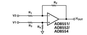
This is a differential amplifier circuit built around the AD8554ARZ, a zero-drift chip that’s perfect when you need high accuracy.
The operation is straightforward: you input two signals, V1 and V2, through a few resistors into the amplifier’s positive and negative inputs. With the right resistor values, the output voltage is simply the amplified difference between your two inputs.
The AD8554ARZ offers incredible precision—only about 1 µV of offset voltage and a tiny drift of just 0.005 µV per degree Celsius. Its low-frequency noise is super low, and it also provides full rail-to-rail input and output, great for battery-powered devices.
You’ll typically see this circuit in sensor measurement setups, medical equipment like ECG machines, and precision industrial control systems.
ad8554arz sensor measurement application
The AD8554ARZ is perfect if you’re measuring tiny sensor signals, like strain gauges, pressure sensors, or thermocouples. Its special “zero-drift” technology means it continuously corrects itself internally, eliminating long-term drift and giving you very accurate measurements.
Let’s say you’re using a strain gauge that outputs only a few millivolts, too small to measure directly. You can connect it in a Wheatstone bridge configuration to the AD8554ARZ, amplifying that tiny signal hundreds or even thousands of times. You simply feed the bridge output into the chip’s inputs and set the desired gain with a precise resistor network. Choose precision resistors, like low-temperature drift metal-film resistors, and pair it with a stable voltage reference for the best accuracy.
ad8554arz low noise amplifier circuit

This circuit uses an AD8554 chip, where two amplifiers (A and B) form a differential input stage to handle your two input signals (V1, V2). The resistor network here is well-designed, significantly cutting down common-mode noise and thermal interference.
There’s another amplifier (C) afterward, which outputs a single-ended amplified signal. You also have an adjustable resistor (R_TRIM) to fine-tune the zero point, minimizing any offset errors or noise even further.
The chip’s zero-drift technology is great—it drastically reduces low-frequency noise and temperature-related drift. It’s ideal for amplifying very small signals. To get the best results, choose a stable, clean power supply and keep your circuit layout neat. This way, you fully leverage the AD8554’s low-noise capabilities.
ad8554arz gain calculation and usage
When designing your circuit with the AD8554ARZ, you’ll set the gain mainly through external resistors. Common setups include non-inverting, inverting, and differential amplifiers.
For example, in a non-inverting setup, gain equals 1 plus the ratio of the feedback resistor to the input resistor. Inverting setups are similar but produce a negative (phase-inverted) output. With differential amplifiers, gain is simply the ratio between feedback and input resistors.
Let’s say you’re using 10kΩ input resistors and 100kΩ feedback resistors in a differential configuration: your gain will be 10. An input of 10mV gives an output of 100mV.
Choose precise, low-temperature drift resistors for accuracy. Higher gain means you’ll need the chip’s ultra-low drift and noise features even more. Place resistors close to the chip to reduce interference, add a small filter capacitor for cleaner signals, and keep your input signals within the 2.7V to 5.5V supply range.
同様のもの

COM8116T-013CD
SMSC
COM8116T-029TMC
SMSC
COM8116T-036P
SMSC
COM8146-6
SMSC
COM8116T-016P
SMSC

COM8116ITP
SMSC

COM5016ATT
SMSC

CRT8002A-003P
SMSC
CRT8002A-034P
SMSC
CRT8002B-033
SMSC
CRT8021H-031
SMSC

CRT7004C-002
SMSC
カートに追加する

MCP1640BT-I/CHY
マイクロチップテクノロジー
TDKEZW3
マイクロチップテクノロジー

IS25LP128-JBLE
ISSI、Integrated Silicon Solution Inc.

MAX3245CAI
アナログ・デバイセズ社/マキシム・インテグレーテッド

PCA9555PW,118
NXP USA Inc.

TPS7B6933QDCYRQ1
テキサス・インスツルメンツ
TMP89FM42UG
東芝

XC6206P182MR
UMW

LM321SN3T1G
オンセミ

T2080NXN8TTB
NXP USA Inc.

ADS8555SPMR
テキサス・インスツルメンツ

ADSP-BF592BCPZ
アナログ・デバイセズ株式会社
関連製品
COM8116T-013CD
SMSC
COM8116T-029TMC
SMSC
COM8116T-036P
SMSC
COM8146-6
SMSC
COM8116T-016P
SMSC
COM8116ITP
SMSC
COM5016ATT
SMSC
CRT8002A-003P
SMSC
CRT8002A-034P
SMSC
CRT8002B-033
SMSC
CRT8021H-031
SMSC
CRT7004C-002
SMSC
COM8116T-013AP
SMSC
COM8116TCO
SMSC
COM8116ATT
SMSC
CRT8002B-0031BICD
SMSC

CRT8002B-020P
SMSC
CRT8002B-032BI
SMSC
CRT8002C-003P
SMSC
COM8136T-5P
SMSC

COM8136BICD
SMSC
COM5026-5P
SMSC
COM5016HR
SMSC
CD40182BCN
フェアチャイルドセミコンダクター
COM5016T-016P
SMSC
COM5016-6CD
SMSC
MC74F280MEL
オンセミ
CRT8002A-005
SMSC
CRT7004B-028BI
SMSC

CRT8002AHR
SMSC
RFQ をお送りください。すぐに対応させていただきます。
