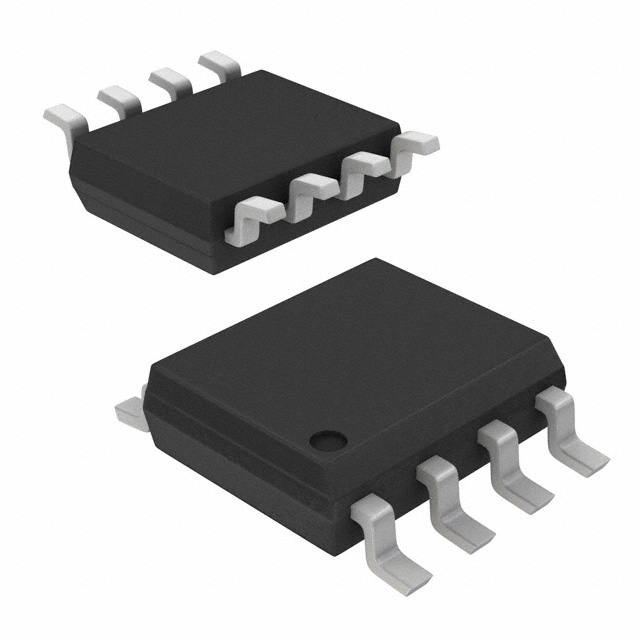
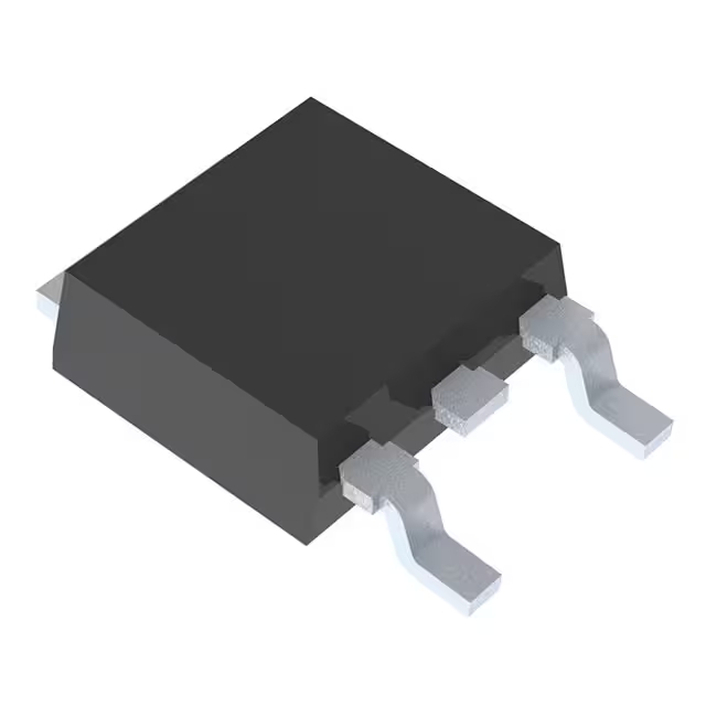
2N7002LT1G | データシート、PDF、価格、SOT23 onsemi
- FETタイプ: Nチャネル
- ドレイン-ソース電圧(Vdss): 60V
- 連続ドレイン電流(Id)@25°C: 115mA(Tc)
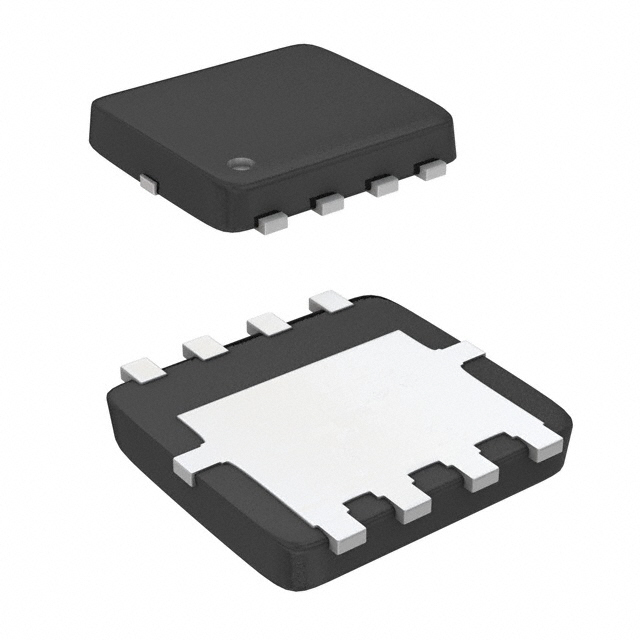
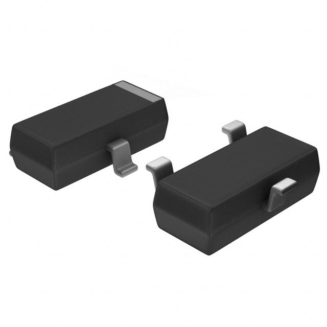
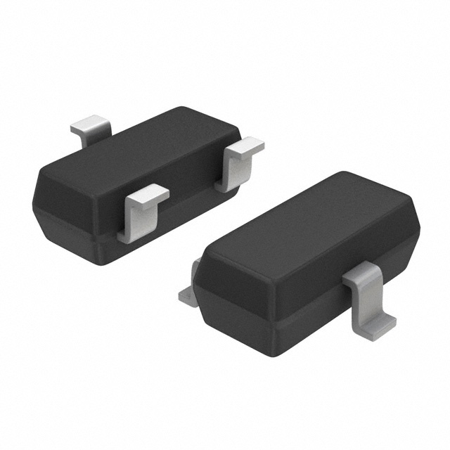
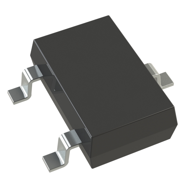
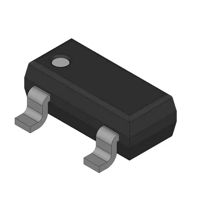
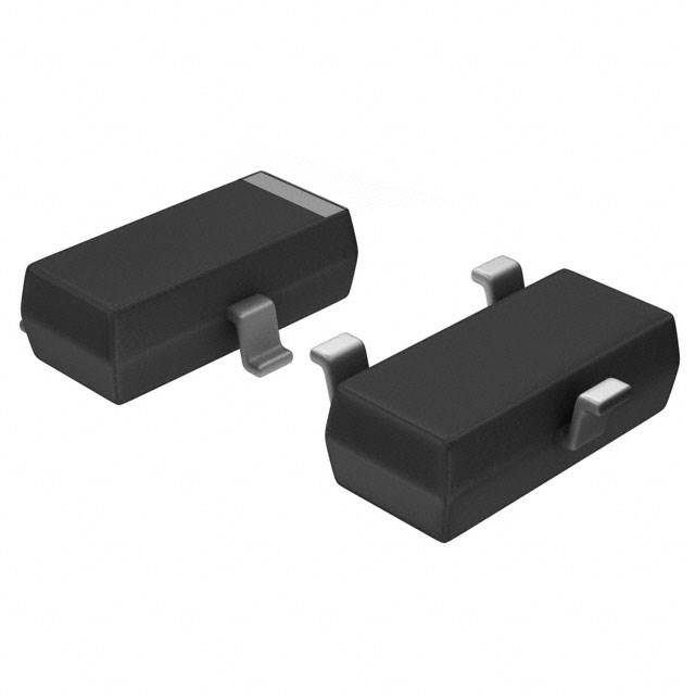
- パッケージ: SOT-23-3(TO-236)

HK$250.00以上のご注文で送料無料

迅速な対応、迅速な見積もり

すぐに発送、アフターサービスも安心

オリジナルチャネル、本物の製品の保証
2n7002lt1g
The 2N7002LT1G is a handy little N-channel enhancement-mode MOSFET that’s great for compact circuits. It comes in a tiny SOT-23 package, perfect if you’re tight on PCB space. This MOSFET handles up to 60V and a continuous drain current of 300mA, with a typical on-resistance of around 1.6Ω at a 10V gate voltage. With a threshold voltage around 2.1V, it easily interfaces with logic signals from microcontrollers (3.3V or 5V).
You’ll find it super useful for low-voltage switching tasks, logic-level shifting, driving microcontroller output ports, or controlling small loads like relays, solenoids, and LEDs.
Just make sure the gate voltage never goes above ±20V, or you’ll risk frying it. Also, keep static electricity in mind; these MOSFETs are sensitive, so handle them carefully. Lastly, design your circuit’s cooling properly to prevent overheating and keep everything running smoothly.
2n7002lt1g pinout diagram & 2n7002lt1g mosfet circuit example

| ピン番号 | ピン名 | 説明 |
|---|---|---|
| 1 | ゲート(G) | Gate pin, controls the MOSFET’s conduction state (on or off). |
| 2 | 出典(S) | Source pin, typically connected to ground or the lower voltage side. |
| 3 | ドレイン(D) | Drain pin, connected to the load or higher voltage side. |
Here’s how to use the pins on your 2N7002LT1G MOSFET clearly and safely.
First, the Gate pin is your input control—apply a logic-level voltage around 3.3V or 5V to switch your MOSFET on or off. Be careful handling this pin, because it’s sensitive to static. Always ground yourself before touching it, especially during soldering or assembly.
その Source pin usually connects directly to ground or your low-side power reference. Think of this as your baseline for switching.
Lastly, the Drain pin goes to your load or higher-voltage source. It’s responsible for carrying the load current. Make sure the current you pass through this pin stays within its limit—no more than 300mA. Exceeding that can damage the component.
Keeping these basics in mind will help you set up reliable and stable circuits with this compact MOSFET.
2n7002lt1g equivalent mosfet

| パラメータ | 2N7002LT1G | BSS138 | DMN2041L | IRLML2502 | AO3400 |
|---|---|---|---|---|---|
| MOSFET Type | N-channel Enhancement | N-channel Enhancement | N-channel Enhancement | N-channel Enhancement | N-channel Enhancement |
| Max Drain-Source Voltage (V_DS) | 60V | 50V | 20V | 20V | 30V |
| Max Drain Current (I_D) | 300mA | 220mA | 1.7A | 4.2 A | 5.8 A |
| R_DS(on) (Typical) | 1.6 Ω | 1.6 Ω | 0.10 Ω | 0.045 Ω | 0.028 Ω |
| Gate Threshold Voltage (V_GSth) | 2.1V | 1.5V | 1.0V | 1.2V | 2.5V |
| パッケージタイプ | SOT-23 | SOT-23 | SOT-23 | SOT-23 | SOT-23 |
その BSS138 can replace it for lower-voltage, low-current situations like logic-level shifting, but it has a slightly lower voltage rating. If you need something stronger for more current but lower voltages, then DMN2041L might be a good fit, just watch out for its lower maximum voltage.
For circuits needing higher currents at low voltages, check out IRLML2502. It offers lower resistance and handles more current easily. Another powerful option is the AO3400, which also features ultra-low resistance and high current capability—but its threshold voltage is a bit higher, making it suitable for situations where you have a slightly higher gate drive voltage.
Always double-check voltage, current, and gate threshold specifications when choosing a replacement. Matching these carefully helps ensure your circuits stay reliable and stable in real-world use.
2n7002lt1g arduino level shifting circuit

When you’re connecting a 3.3V device, like a sensor, to a 5V Arduino, you’ll often need a reliable way to shift the signal levels safely. The 2N7002LT1G MOSFET works great for this job, especially for I²C communication, because it allows signals to flow both ways.
Here’s how it works: when your 3.3V side pulls the line low, the MOSFET’s internal diode immediately brings the 5V side down as well. If the 5V side goes low first, the MOSFET itself turns on—thanks to the gate voltage at 3.3V—quickly sending the signal back to the 3.3V side.
Use 10kΩ pull-up resistors on both sides to maintain a stable high level. For faster communication, switching these to 4.7kΩ helps signals rise quicker.
Pay close attention to the MOSFET’s orientation and internal diode direction when building your circuit. Keep these basics in mind, and your Arduino will communicate smoothly between different voltage devices every time.
2n7002lt1g use in load switch circuit

If you’re building a load switch controlled by a microcontroller, the 2N7002LT1G MOSFET can simplify your job. Here’s how it works:
When your microcontroller output is low (under about 1.8V), the control MOSFET (Q2, your 2N7002LT1G) stays off. That means resistor R1 pulls up the gate of your main MOSFET (Q1), turning it on, and letting current flow from VIN straight to your load.
Now, when your microcontroller goes high (typically 2.5-3.3V, above the MOSFET’s threshold), Q2 switches on, quickly pulling Q1’s gate voltage down via R2. This shuts off Q1 instantly, cutting off power to the load.
Choose your resistors carefully: too large slows down switching, too small may cause excess current. Also, be cautious with capacitor C1—use just enough to stabilize the gate without slowing things down.
Overall, the 2N7002LT1G is perfect here: compact, quick-switching, and efficient, helping your design stay clean and reliable.
2n7002lt1g as a relay driver
When you’re controlling a relay with your Arduino or Raspberry Pi, a MOSFET like the 2N7002LT1G can simplify your setup compared to traditional transistors. MOSFETs switch faster, require less drive current, and have higher input resistance, making them perfect for low-voltage digital control circuits.
Here’s how it works: connect your microcontroller GPIO pin to the gate of the 2N7002LT1G through a resistor (around 100Ω is good), its source directly to ground, and its drain to the relay coil’s negative side. The coil’s positive goes to your supply voltage (like 5V or 12V).
Always add a flyback diode (like a 1N4007 or 1N4148) across your relay coil to safely absorb voltage spikes when switching off, protecting your MOSFET. And remember, ensure your relay coil current stays below about 200mA—otherwise, choose a stronger MOSFET.
Finally, make sure your GPIO voltage (3.3V or 5V) comfortably exceeds the MOSFET’s threshold voltage (typically around 2.1-2.5V) for reliable switching.
2n7002lt1g mosfet gate drive design
When you’re designing a MOSFET gate drive circuit—like one using the 2N7002LT1G—your main goal is to switch it quickly and smoothly without noise or voltage spikes that could damage it.
You’ll typically connect your microcontroller GPIO pin through a gate resistor (around 50Ω to 220Ω is best) to limit the charging current of the MOSFET’s gate. This resistor prevents damaging voltage overshoots and reduces high-frequency ringing. Don’t go too large with this resistor, though, or your MOSFET might switch too slowly, causing extra heat and inefficiency.
Keep in mind the gate threshold voltage for the 2N7002LT1G is about 2.1–2.5V, so always drive it from a microcontroller pin at 3.3V or 5V to ensure full switching.
Also, watch out for parasitic gate capacitance—it’s small but matters at high speeds. For inductive loads like relays or motors, always include a flyback diode for protection.
Lastly, keep your PCB layout tight to minimize noise and interference.

~~3.jpg)



.jpg)





.jpg)
