
SCA100T-D01-1 Datenblatt & Preis | pdf
- Marken: Murata Electronics
- Herunterladen: SCA100T-D01-1 Datasheet PDF
- Preis: Anfrage
- Auf Lager: 6,731
- Empfindlichkeit: 4V/g
- Bandbreite: 8 ~ 28Hz
- Nennspannung: 4,75 V bis 5,25 V
- Paket: 12-SMD, L-Bend


KOSTENLOSE Lieferung für Bestellungen über HK$250.00

Schnelle Reaktion, schnelles Angebot

Blitzversand, keine Sorgen nach dem Verkauf

Originalkanal, Garantie der authentischen Produkte
SCA100T-D01-1
If you’re looking for a reliable sensor to measure tilt angles in multiple directions, this dual-axis inclinometer could be exactly what you need. It accurately measures tilt along both the X and Y axes, with a range of ±30°, ideal for applications that require precise multi-directional orientation detection. With its high sensitivity of 4 V/g, it’ll pick up even the smallest angle changes, making it perfect for precision-critical setups.
You also get flexibility with bandwidth, adjustable from 8 to 28 Hz, allowing you to fine-tune the sensor’s response to your specific scenario. Integration is easy too, thanks to both analog voltage and digital SPI outputs that fit neatly into your existing control systems.
Power isn’t an issue—it runs comfortably on voltages between 4.75 and 5.25 V. Plus, it’s built for tough environments, handling temperatures from -40°C all the way up to +125°C. Its compact, 12-pin SMD package (15.6 × 11.3 × 5.1 mm) makes it easy to fit into tight spaces, whether you’re working with industrial automation, structural monitoring, agricultural machinery, or robotic systems navigating challenging terrain.
SCA100T-D01-1 Pinout & SCA100t-D01-1 Spi Interface Wiring

| PIN-Nummer | Pin-Name | Funktionsbeschreibung |
|---|---|---|
| 1 | VDD | Power Supply Input (+5V) |
| 2 | Masse | Ground (Negative power supply) |
| 3 | OUT_1 | X-axis tilt analog output |
| 4 | OUT_2 | Y-axis tilt analog output |
| 5 | SCK | SPI Clock Input |
| 6 | MISO | SPI Master Input Slave Output |
| 7 | MOSI | SPI Master Output Slave Input |
| 8 | CSB | SPI Chip Select (Active Low) |
| 9 | ST1 | Self-test Control Pin 1 |
| 10 | ST2 | Self-test Control Pin 2 |
| 11 | NC | Reserved Pin (Not Connected) |
| 12 | NC | Reserved Pin (Not Connected) |
When you’re wiring up this sensor, there are a few important pins you’ll want to pay attention to. First off, make sure you provide a stable 5V power supply to the VDD pin and properly connect your ground (GND) to ensure reliable operation.
You’ll notice two analog outputs labeled OUT_1 and OUT_2. These pins send out analog voltage signals corresponding to your X and Y tilt angles. To keep measurements accurate, connect them to high-impedance analog inputs to avoid loading effects.
There’s also an SPI interface with pins labeled SCK, MISO, MOSI, and CSB. Use this if your control system communicates digitally—just make sure the clock frequency and voltage match the sensor’s specifications.
If you’re not planning to use the sensor’s self-test feature, it’s best to leave the ST1 and ST2 pins floating or tie them to ground. Lastly, you’ll see some NC (no connect) pins—these aren’t currently used, so leave them disconnected to avoid any unwanted interference.
SCA100T-D01-1 Equivalent Tilt Sensor
| Parameter | SCA100T-D01-1 | SCA100T-D02-1 | SCA3300-D01-1 |
|---|---|---|---|
| Measurement Axes | Dual-axis (X, Y) | Dual-axis (X, Y) | Tri-axis (X, Y, Z) |
| Measurement Range | ±30° | ±90° | ±1.5g / ±3g / ±6g |
| Output Type | Analog Voltage / SPI | Analog Voltage / SPI | SPI (Digital) |
| Sensitivity | 4 V/g | 4 V/g | Configurable (depending on measurement range) |
| Bandbreite | 8 ~ 28 Hz | 8 ~ 28 Hz | 0.1 ~ 100 Hz |
| Betriebsspannung | 4,75 V bis 5,25 V | 4,75 V bis 5,25 V | 2,7 V bis 3,6 V |
| Pakettyp | 12-pin SMD | 12-pin SMD | 12-pin SMD |
| Betriebstemperatur | -40°C ~ +125°C | -40°C ~ +125°C | -40°C ~ +125°C |
| Status | Discontinued | Discontinued | Auf Lager |
| Typische Anwendung | Industrial tilt measurement | Industrial tilt measurement | High precision motion and tilt measurement |
| Price Reference | — | — | $35.36 (Digi-Key) |
If you’re considering sensor replacements, here’s a quick rundown: The SCA100T-D02-1 matches your original SCA100T-D01-1 closely but measures angles up to ±90°, ideal if you need greater tilt detection. The SCA3300-D01-1 is another good option—it adds Z-axis measurement, runs at 3.3V, and uses a digital SPI output instead.
Before swapping sensors, double-check your interfaces and voltages to avoid compatibility issues. Remember, switching from analog to digital outputs will require software updates. Also, verify pin layouts and dimensions carefully for seamless installation. Always choose your replacement based on your exact requirements to keep your system stable and reliable.
SCA100T-D01-1 Inclinometer Circuit Design
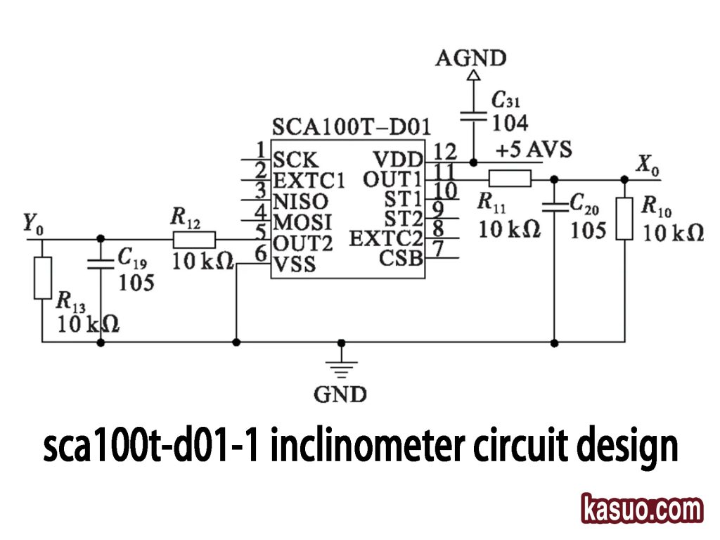
This simple circuit design uses the SCA100T-D01 dual-axis inclinometer. You just supply a stable +5V power with a 0.1µF capacitor (C31) for filtering. The analog outputs (OUT1, OUT2) measure X/Y tilt angles and pass through low-pass filters (R10–R13, C19, C20) to smooth the signal. SPI and self-test pins aren’t connected here, keeping things straightforward—perfect for accurate, reliable tilt measurements.
SCA100T-D01-1 Application in Robotics
If you’re building robots, this inclinometer sensor could be exactly what you need. It helps your robot keep balanced and stable, whether it’s on wheels, tracks, or legs, by instantly measuring ground tilt. Robotic arms can use it too, making precise, controlled movements much easier. It’s perfect for navigating tricky terrain—like disaster zones or uneven farmland—ensuring safe and accurate paths. Plus, it alerts you if tilt angles exceed safety limits, preventing accidents. With high accuracy, noise resistance, and dual outputs (analog and SPI), integrating it into your robotics project is simple, reliable, and efficient.
SCA100T-D01-1 Tilt Measurement Example
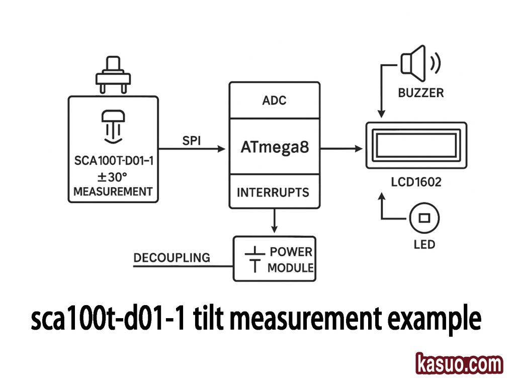
Here’s an easy way you can set up a dual-axis tilt measurement system. Start with the SCA100T-D01-1 sensor, which accurately measures tilt angles within ±30°. Connect this sensor via SPI to an ATmega8 microcontroller—it’ll handle reading data and trigger alerts when certain thresholds are crossed. You’ll display real-time tilt values clearly on an LCD1602 screen. And just to make sure you don’t miss any critical changes, a buzzer and LED will activate if your tilt exceeds the safe limits. Don’t forget a stable 5V power module with decoupling capacitors to keep your readings reliable.
SCA100T-D01-1 With Arduino

When you start up your system, you’ll first set up the SPI communication, configure your LCD display, and initialize any interrupts you need. Next, you’ll regularly grab the X and Y tilt data from your SCA100T-D01-1 sensor through SPI. Once you have that data, you’ll calculate the actual tilt angles. Then, simply show those angles right on your LCD. And here’s the smart part—if your measured angles ever cross certain limits you’ve set, a buzzer and LED will immediately alert you, so you’ll always know if something needs your attention.
SCA100T-D01-1 Industrial Tilt Sensor
If you’re working in industrial applications, here’s how the SCA100T-D01-1 sensor can really make your job easier and safer. For heavy machinery like cranes, excavators, or construction equipment, you can use it to monitor tilt in real-time and avoid dangerous tipping accidents. If you’re monitoring bridges, dams, or tall buildings, it’ll instantly alert you to any abnormal structural movement, helping you catch issues early. It also enhances rail safety by detecting tilts on trains or tracks, preventing derailments. On production lines, it ensures precise positioning and control, boosting efficiency and cutting errors. In agriculture or forestry equipment, it’ll help you navigate uneven terrain safely. Even wind turbines can benefit—keeping structures stable by providing early tilt warnings. Its accuracy, durability, wide operating temperature range, and flexible analog/SPI interfaces make it ideal for demanding industrial environments.
SCA100T-D01-1 vs SCA100t-D02-1
| Parameter | SCA100T-D01-1 | SCA100T-D02-1 |
|---|---|---|
| Measurement Axes | Dual-axis (X, Y) | Dual-axis (X, Y) |
| Measurement Range | ±30° | ±90° |
| Sensitivity | 4 V/g | 2 V/g |
| Output Type | Analog Voltage / SPI | Analog Voltage / SPI |
| Bandbreite | 8 Hz ~ 28 Hz | 8 Hz ~ 28 Hz |
| Betriebsspannung | 4,75 V bis 5,25 V | 4,75 V bis 5,25 V |
| Betriebstemperatur | -40°C ~ +125°C | -40°C ~ +125°C |
| Paket | 12-pin SMD | 12-pin SMD |
| Application Scenario | Small-range precision tilt measurement (Industrial, Robotics) | Larger-angle measurement (Vehicles, Construction Machinery) |
| Status | Discontinued | Discontinued (Limited stock) |
Looking at the comparison, you’ll notice two main differences between the SCA100T-D01-1 and SCA100T-D02-1 sensors: their measuring range and sensitivity. The D01-1 model works best when you’re measuring smaller angles up to ±30°, perfect for precision tasks like fine robotic controls or detailed industrial setups. Its higher sensitivity (4 V/g) gives you sharper accuracy. On the other hand, the D02-1 covers a broader range (±90°), making it ideal if your application involves bigger movements, such as machinery positioning or vehicle monitoring, though its sensitivity drops to 2 V/g. Keep in mind both models have been phased out, so I’d recommend shifting toward newer alternatives like the SCA3300 series to make sure you won’t run into availability issues later on.
SCA100T-D01-1 Calibration Method
First, you want to set things up properly. Make sure you have a stable 5V power supply connected to your sensor, and once powered, let it warm up for around two minutes to reach a steady state. Position it carefully on a flat, level surface to ensure no tilt affects the readings.
Next, it’s important to calibrate your zero point. With your sensor placed perfectly level, note down the X and Y output readings—these values represent your zero offset. Save them into your microcontroller or processor. Whenever you take future measurements, subtract these saved zero offsets from the sensor’s readings for accurate tilt angles.
Lastly, you’ll calibrate sensitivity. Tilt your sensor precisely to known angles (like ±30°) along both X and Y axes, then record those outputs. By comparing the outputs to the actual angles, you’ll determine your sensor’s sensitivity in volts per degree (V/°). Adjust your measurements accordingly, and you’ll greatly enhance the precision of your results.
Ähnliche Artikel

SCM9B-PB08
DATAFORTH

MC33941EGR2
NXP USA Inc.

50-04-0063-02R
Finisar Corporation
50-11-0105-02R
Finisar Corporation
50-04-0031-01R
Finisar Corporation
50-11-0250-01R
Finisar Corporation
50-11-0199-01R
Finisar Corporation
50-04-0085-02R
Finisar Corporation
1187177
Finisar Corporation
50-11-0235-01R
Finisar Corporation
50-04-0040-02R
Finisar Corporation
FOA-M2300CD-EFV1C-CY032
Finisar Corporation
Auch in den Warenkorb legen
SPCM-AQRH-60-FC
Excelitas Technologies

TLV493DA1B6HTSA2
Infineon Technologies

USEQFSM1448100
KEMET

TMP235AEDCKRQ1
Texas Instruments

SCMVAS-M100
DATAFORTH

SCM7B37K-22A
DATAFORTH
E3X-MDA8
Omron Automatisierung und Sicherheit

A1262LLHLT-T
Allegro MicroSystems
SPCM-AQRH-40-BR1
Excelitas Technologies

AS-MLV-P2
ScioSense

33247
SpotSee
.jpg "LIS2DW12TR")
LIS2DW12TR
STMicroelectronics
Verwandte Produkte
SCM9B-PB08
DATAFORTH
MC33941EGR2
NXP USA Inc.
50-04-0063-02R
Finisar Corporation
50-11-0105-02R
Finisar Corporation
50-04-0031-01R
Finisar Corporation
50-11-0250-01R
Finisar Corporation
50-11-0199-01R
Finisar Corporation
50-04-0085-02R
Finisar Corporation
1187177
Finisar Corporation
50-11-0235-01R
Finisar Corporation
50-04-0040-02R
Finisar Corporation
FOA-M2300CD-EFV1C-CY032
Finisar Corporation
50-11-0133-01R
Finisar Corporation
50-11-0218-01R
Finisar Corporation
FOA-R9300TH-HBR3C-AA001
Finisar Corporation
50-04-0081-01R
Finisar Corporation
FOA-M2200CB-EFG1C-XK064
Finisar Corporation
1184258
Finisar Corporation
50-04-0039-02R
Finisar Corporation
FOA-R9300TH-HBR3C-AA048
Finisar Corporation
FOA-R9100DJ-RBW2C-AA047
Finisar Corporation
FOA-M2200PB-EFG1C-AA067
Finisar Corporation
50-11-0075-02R
Finisar Corporation
50-11-0071-03R
Finisar Corporation
50-11-0182-01R
Finisar Corporation
50-04-0080-02R
Finisar Corporation
FOA-M2200CB-EFG1C-AA500
Finisar Corporation
50-11-0215-01R
Finisar Corporation
50-04-0108-01R
Finisar Corporation
50-04-0003-03R
Finisar Corporation
Bitte senden Sie eine RFQ, wir werden umgehend antworten.
