Voltage Dividers: Why They Are Important in Circuits and How They Work
Author:admin Date: 2025-04-28 08:52 Views:135
Introduction
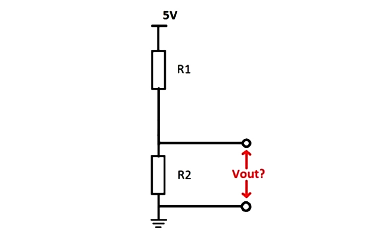
A voltage divider is a simple electronic circuit used for producing an output voltage that is lower than the input voltage. Most of the time, the output voltage is only a fraction of the input voltage.
Voltage dividers consist of resistors connected in series to make its functionality possible. The output voltage is measured in between the resistors. Expect that such a device will have applications where it is necessary to reduce the voltage in the circuit to a more manageable level that works for specific devices.
Key Components of Voltage Dividers
The primary components of voltage dividers are resistors. These are responsible for determining the amount of voltage division and voltage output in the circuit.
For example, you can have two resistors, R1 and R2. These two resistors will be connected in series. The ratio of their restances determines the amount of output voltage.
In addition to resistors, you have a voltage source (Vin) and an output voltage (Vout). The output voltage value across R2 is usually a fraction of the input voltage.
How Voltage Dividers Work
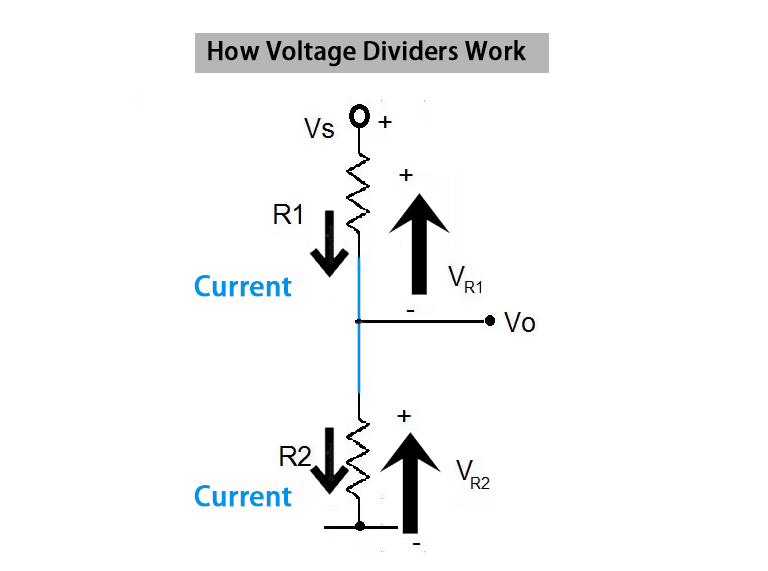
We will consider the example of two resistors, R1 and R2, in series. The voltage is applied across these two resistors to see how much of the voltage drop will happen in the end.
The current flowing cross the two resistors is the same since they are in a series connection. However, the voltage drop is proportionate to the resistance value of each resistor.
To calculate the output voltage, use the voltage divider equation shown below.
Vout = Vin * (R2/(R1 + R2))
Benefits of Using Voltage Dividers
A voltage divider circuit is likely to have many benefits than what most people think. For example, the desired output voltage can be obtained by adjusting the resistors used in the circuit. You can reduce the high voltage to an required level for a certain device.
A resistor voltage divider can also help adjust signal levels. It is now possible to reduce the signal amplitude making it compatible as an input signal for specific measuring devices.
You can also have voltage dividers in transistor circuits. They will be essential for setting the base voltage that transistors need for proper operation.
The use of a potentiometer voltage divider allows you to vary the output voltage by adjusting the amount of resistance introduced into the circuit. You should find such an operation good for tuning circuits.
In terms of cost, the voltage dividers are generally cheap to design and implement. This is because you only need to use two resistors for the operation, making them a cost effective solution.
Types of Voltage Dividers
Voltage dividers can be categorized into resistive, capacitive, and inductive. It all depends on the components used in the circuit to realize a lower voltage than the input voltage.
Resistive Voltage Dividers

These dividers have resistors that help create the voltage drop. The output voltage is only a fraction of the input voltage. This is determined by the ratio of the resistor values. Expect to come across such dividers in DC circuits and are easy to implement.
Capacitive Voltage Dividers
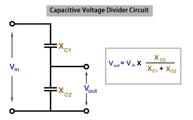
These dividers utilize capacitors instead of resistors to act as voltage divers in the AC circuits. The AC frequency and capacitance of the capacitors determines the output voltage. This makes them ideal for filtering and signal processing applications.
Inductive Voltage Dividers

Inductors are the key components used in dividing the voltage in the circuit. They are particularly useful in RF applications and high-frequency circuits. They are not as common as resistive voltage dividers, but come in handy for RF amplifiers and antenna tunning applications.
Adjustable Voltage Divider

The adjustable voltage dividers use potentiometers, which allow for adjusting the output voltage. Sometimes you may need to vary the output voltage to a precise value. Well, if you get a good setup, this circuit would be ideal for calibration of equipment.
Limitations of Voltage Dividers
Although voltage dividers have many uses, they also have some limitations. Below are notable limitations of voltage dividers you should know.
Power Inefficiency
Voltage dividers can sometimes be power inefficient. This is especially true when using smaller resistors to handle changes in load resistance. The result is having wasted power.
Load Variation and Accuracy
The output voltage of a voltage divider can only be accurate when there is minimal or no load current. When you increase the load current, the output voltage becomes less accurate due to higher voltage drop across the resistors.
High Frequency Applications
Resistive voltage dividers are not the best for high-frequency applications. This is because their accuracy degrades a lot at higher frequencies.
How to Design Voltage Dividers for a Circuit
There are several things to consider when designing a capacitor voltage divider or a resistive voltage divider. Here is what to put in mind:
- Determine what is the desired output voltage. This is crucial as it determines the components you will use for the circuit.
- Know your input voltage. What is the starting voltage?
- Calculate your resistance ratio. This is done by dividing the output voltage by the input voltage. The value you get is the desired voltage reduction ratio.
- Choose the value for R1. This is the resistor connected to the ground. Choose any value for this resistor.
- Once you have the R1 value, use it to calculate the value for R2. This is done by multiplying the value of R1 by the voltage reduction ratio.
- You can use the general voltage divider formula to verify that the values give you the desired voltage.
Common Mistakes to Avoid When Working With Voltage Dividers
The principle of voltage divider works quite well for different applications, but sometimes mistakes can make the voltage dividers inefficient. Here are some of them.
Ignoring the loading effects happens more often than you think. When using a resistor as voltage divider, people usually assume no load, but in reality there can be a load connected to the output which affects the voltage divider’s behavior. The loading effect can lead to high voltage drops.
Choosing unsuitable resistor values is another mistake people make. Some often choose low resistor values, meaning the voltage divider can draw excessive current, thus making the resistors overheat. Conversely, using very high resistor values means the voltage divider is too sensitive, even to small changes in the input voltage, thus making it unreliable.
When you ignore resistor tolerances and temperature effects, this can lead to unexpected voltage drops or too much variations in the output voltage. People need to understand that resistors have tolerances and their actual working values might differ slightly from the nominal values.
These are just some of the mistakes people make. Take the time to understand the application and choose the right components for it.
Voltage Dividers vs. Voltage Regultors
We already know how a voltage divider works. It is simply a circuit having two or more resistors in series across a voltage source. The job of such a circuit is to divide the input voltage according to the resistor ratio, resulting in a much lower output voltage.
Applications for voltage dividers include voltage biasing, level shifting, and signal conditioning.
A voltage regulator is a type of active circuitry whose job is to maintain a constant output voltage. This is true regardless of variations in load current or input voltage. You will come across two main types of voltage regulators. They include linear regulators and switching regulators.
Applications for voltage regulators include power supplies, battery charging, and providing regulated voltages for different types of circuits.
Conclusion
Voltage dividers are key in many applications. As long as you need a lower output voltage, this is an example of how to do it. The best part about voltage dividers is how easy they are to implement. Once you know how to use the voltage divider formula, it shouldn’t be hard to design a voltage divider and implement it. Make sure to avoid the mistakes we have mentioned above to have a good working voltage divider for your application.


