Serial Peripheral Interface (SPI)? Components, and How It Works
Author:admin Date: 2025-04-25 03:32 Views:57
Introduction
A serial peripheral interface or SPI is a type of synchronous serial communication interface that is used for short distance data transfer from a master device to one or several slave devices. This type of system is common in embedded systems due to its high speed performance and simplicity as well.
SPI operates on a master/slave architecture. This means that the master controls the communication while the slave devices respond based on its commands.
If this is the first time you are coming across serial peripheral interface, you have nothing to worry about as we take a deep look at this interface to help you understand it better. This includes describing how it works and its common applications.

Features of the Serial Peripheral Interface (SPI)
The (SPI) serial peripheral interface remains a popular choice for many applications. The reasons lie in the features it offers. Here is what to expect.
- It offers synchronous communication. This means that data transfer happen at the same time as a clock signal. This is vital to ensure the master and slave devices are always in sync.
- It uses the master/slave architecture. In this case, you have one device which is the master that controls the communication and clock. The other devices, slaves, receive the instructions from the master on what to do.
- SPI offers full duplex communication. This means that SPI can transmit data in both directions. A master device can send data to a slave device, and at the same time, the slave device can send data back to the master device.
- The interface is designed for high speed operations. Expect the communication between devices to be very fast. This makes it suitable for applications requiring high transfer rates.
- The serial peripheral interface bus protocol is best suited for short distance communications. Expect it to be used mostly for single circuit boards.
- The common use cases for SPI include communication between the peripheral devices such as ICs, sensors, and the microcontroller. For example, using the Serial Peripheral Interface (SPI) for Arduino.
- Flexibility is another reason to consider the serial peripheral interface busfor your needs. This is because designers can add multiple slave devices as needed. You simply need to add additional SS lines making the system flexible to suit your communication needs.
Components of the SPI Protocol

Now that you know what is serial peripheral interface, let us look at the components that make it possible for the interface to work.
1. Master Device
The work of the master device is to control the communication process between it and the slave devices. In addition to controlling the communication, it also generates the clock signal vital for synchronizing with the slave devices. An example of a master device is a microcontroller.
2. Slave Device
This is a peripheral device connected to the master device via an SPI (Serial Peripheral Interface) protocol bus. Each slave device in the circuit will have its dedicted slave select or SS line that allows the master device to communicate with it directly.
3. SPI Bus

This is the physical connection between the master and slave devices. It contains four signal lines that enable data transfer. They include slave select (SS), Master Out Slave In (MOSI), Master In Slave Out (MISO), and Serial Clock (SCK).
For Slave Select, each device comes with a dedicated SS pin. This means that the master device uses this dedicated pin to communicate with a specific slave in the circuit. Although each device will have a dedicated SS line, they can share the MOSI, MISO, and SCK lines.
The Master Out Slave In bus is for sharing data from the master device to the other slave devices on the business.
As for Master In Slave Out bus, it used to share data from the slave to the master device.
The Serial Clock is a vital part of the bus, as its clock signal is used to synchronize data transfer between master and slave devices, ensuring accurate data transfer.
4. Data Transfer Protocol
This is the protocol used for data transfer between master and slave devices, or vice versa. It works by generating clock pulses that initialize the transfer from the master to the slave device. For each clock cycle, one bit of data is transmitted from the master to slave devices and vice versa since it is a full duplex type of communication.
5. Data Rate
This is how fast the data can move between devices connected via the SPI. It largely depends on the capabilities of the master device and the slave devices as well. Also, the length of the transmission line is vital. It is measured as bits per second (bps) or per megahertz (MHz).
6. Clock Phase (CPHA) and Clock Polarity (CPOL)
These two determine the clock’s state during communication. CPOL determines the idle stage of the clock signal. This is either high or low. As for the CPHA, it determines when the data on the clock edge is sampled. It can either be rising or falling.
How the Serial Peripheral Interface Works
With the description of the serial peripheral interface (SPI) components above, it is easy to see how it operates.
It starts with the master device initiating the communication. It does this through sending a clock signal to help sync the data transfer with the slave device.
The data is then placed on the MOSI line and sent to the slave device. The slave device can share information back to the master using the MISO line.
Each bit of information is accompanied by a clock pulse. This is vital for ensuring there is a synchronous communication between the device. Also, the communication is full-duplex, meaning data can be transmitted in both directions.
Common Applications of SPI
Expect to come across this type of interface for communication between microcontrollers and its peripheral devices. For example, it is a common protocol using in embedded systems.
Below are the key applications of the Serial Peripheral Interface (SPI) protocol.
- SPI is used to interface different types of sensors. Examples include temperature, light, and pressure sensors, which allow the microcontroller to read data from them.
- A display can also use this protocol too. This allows the microcontroller to display information.
- SPI is also widely used with memory chips such as flash memory. It enables data storage and ease of retrieval of the same data.
- SD cards and RFID readers need this type of protocol for reading and storing information on the devices.
You can expect to come across several other applications as you explore the SPI protocol.
How to Test an SPI with Oscilloscopes
Using an oscilloscope can help you analyze the SPI signal to know if it is working as expected. Below are the steps you can use to test and analyze the signal.
Connect the Oscilloscope Probes
- Attach the probes to the MOSI line for monitoring the data from the master to slave.
- Do the same for the MISO line to observe the data transfer from slave to master
- Attach probes to the SCLK which is the serial clock line for capturing the clock signal from the master device.
- Connect probes to the slave select or SS line to see when the master communicates to a specific slave.
- Ensure all the probes are grounded as a good measure, which minimizes noise and improves accuracy.
Setting up the Oscilloscope
- Adjust the oscilloscope’s time base to suit the clock frequency so that you can see the SPI signals correctly.
- You should also set the trigger for the SCLK signal to stabilize the waveforms, making them easier to read.
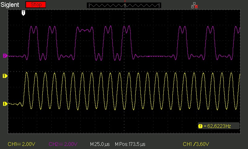
Analyze the Waveforms
Once you have connected the probes and have done the setup correctly, you should start seeing the waveforms. Make sure that your SCLK signal is clean and running at the expected frequency.
Monitor the MOSI and MISO lines to check if data transfer is occurring and at the correct timing.
Use the Oscilloscope to measure the pulse width, timing intervals, and other important signal parameters.
Look for errors in the waveform to ensure there are no protocol violations.
Pros and Cons of SPI
Pros
- Expect to get high speed data transfer between devices. This makes it good for applications such as display controllers, flash storage, and memory chips.
- It offers full duplex communication. This is important for simultaneous data transmission and reception improving efficiency.
- SPI has a straightforward design and working principle. This means designing and implementing should be easy.
- This enhanced serial peripheral interfacehas a low pin count. With only four lines, it means less pin usage and more effective than some parallel communication methods.
- Unlike other data transmission methods, SPI uses dedicated communication lines between the master and slave devices. As such, no more complex addressing schemes.
- There is no need for a central bus or transceiver, as there is direct device-to-device communication. This helps to reduce the number of components in the setup.
Cons
- Expect the protocol to have more physical lines since each device needs its dedicated link with the master.
- The protocol is best suited for short-distance communication. So, its applications can also be limited.
- SPI lacks a system for checking errors, which can be critical in some applications.
- Having to run multiple slave devices can complicate the whole set up. This is because you have to run separate select lines to each slave.
- Sometimes, there can be signal degradation at longer distances or if the wiring is of poor quality. This may impact data integrity.
Troubleshooting SPI Common Issues
You may run into some issues while working with the SPI protocol. Below we look at some ideas on how to handle these issues ensuring the devices can communicate and keep the operation going.
Physical Connections
Make sure that you verify the wiring between the master and slave devices. If they are loose, then the devices will not work as expected.
Check that both devices have a common ground and there is adequate power supply.
As for those with multiple slaves, ensure that each has its own SS pin to allow communication between it and the master device.
SPI Parameter Configuration
Use the correct settings for the clock polarity and phase of the device. Refer to the datasheets to set the proper settings, as they determine when your data is sampled.
Look at the clock speed and ensure it is within the supported range by both the slave and master devices.
Also, look at the clock modes. Each mode defines how a clock behaves and when the data is sampled. The idea is to have both the slave and master devices using the same mode.
Device Communication
This is a test to check the communication and ensure everything is working as expected. For example, ensure that the slave’s data is clocking out correctly just as the master data.
How is the slave device behaving? Check to see if behaves as expected when you pull the MISO line. You can switch between slaves to know the performance and behavior. Sometimes you can have a faulty line and when you interchange slaves, one works and the other does not.
Troubleshooting Tools
An oscilloscope is a great tool for visualizing SPI signals and identifying issues with timing or signal integrity.
A logic analyzer is another useful tool for capturing and analyzing SPI bus traffic. It helps pinpoint where a communication issue might be.
A protocol analyzer is another useful tool to have. This is a specialized tool for decoding SPI data, providing detailed information about the communication so you can identify any issues.
Software Issues
Sometimes, software issues can cause the system to behave abnormally. So, review the SPI initialization code for possible errors. It could be incorrect parameter settings or sometimes conflicts with other devices connected to the master.
Also, look out for possible timing issues. Sometimes, you may need to add delays to the code to ensure proper timing when sending more than a few bytes. Reading more serial peripheral interface tutorials can help with resolving timing issues.
Serial Peripheral Interface Best Practices
There are a couple of things you should do if you want the SPI protocol to work good for your application. Here’s what to keep in mind.
- Having a proper hardware design can make a big difference in the overall functionality of the setup. We recommend biasing the unused inputs to a specific logic state to prevent cases of random floating and potential device malfunction.
- Software implementation should also be done right. This includes having a clear communication protocol that defines the communication in advance. This consists of the data formats and timing.
- Consider configuring the threshold levels for data buffers. This is key to controlling the frequency of data handling events.
- Data packing is also important as it helps with efficient data transfer. It is recommended when using a wider access method such as DMA.
Conclusion
The SPI protocol remains a good option for various applications. This is thanks to its functionality, ease of implementation, and scalability. Even though it may have a few limitations, such as a limited range, you can expect it to perform well in its intended applications. We have also discussed best practices for ensuring the protocol works best for you. Follow these practices, along with many others, to unlock the full potential of the SPI protocol.


