How to Use a Multimeter For Beginners: Expert Guide to Get You Started
Author:admin Date: 2025-04-25 08:25 Views:46
Introduction
A multimeter, whether analog or digital, is a crucial electronic device used for measuring different types of electrical properties, such as resistance, current, and voltage, of a circuit. The multimeter has a display where it shows the values depending on what is being measured.
It’s a simple device to use, but not everyone knows how it works. That is why this guide looks at how to use a multimeter for beginners to get you started. We will delve deeper into fully understanding how best to use a multimeter to measure different electrical properties.
Components of a Multimeter
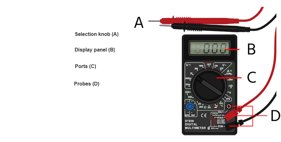
The notable components of a multimeter include the display, ports or sockets, probes, and the selection knob.
The display gives you the values of the measured property across a component. It could be a digital display or a needle movement depending on the type of multimeter.
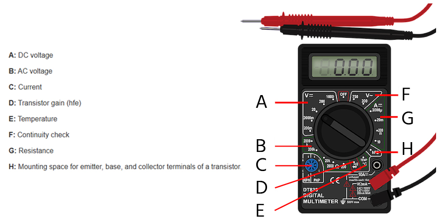
The selection knob or switch is vital for allowing the user to choose the desired measurement function. This includes the voltage, resistance, or current. You can choose the appropriate function depending on the component or property you need to measure.
The probes or test leads are flexible wires with clips or probes at the end. One side is inserted into the multimeter, and the other end, with a clip, attaches to the component to be measured. The probes are either black or red. Black is for the negative terminal and red is for the positive terminal.
Ports are also called jacks or terminals. This is where you insert the probes to test a property. The Common port is the ground connection. This is where you connect the black probe. As for the other ports, they will be labelled depending on functionality. This is where you connect the red probe depending on the label.
You are likely to get more components depending on the type of multimeter you have. This includes controls or buttons that allow you to select a range or type of electrical property to measure. Follow the user manual for your multimeter to understand its capabilities fully.
Types of Multimeters
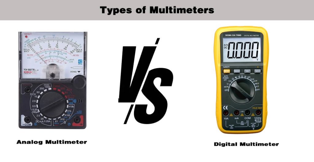
Multimeters are broadly classified as either analog or digital. Each will result in the same measurement, but they just have a different working principle and parts as well.
Analog Multimeter
These are quite common multimeters in the market. They feature a pointer vital for indicating the value of an electrical property. The scale is broken into different types depending on what you want to measure.
Such a device is suitable for working on various components and does not require a power supply to operate, especially when measuring basic current and voltage properties.
However, they can be less accurate compared to digital multimeter. This is because you have to read correctly yourself. It needs practice to avoid parallax errors.
Digital Multimeter
This one has a display that converts the analog signal into a digital signal and displays it.
These multimeters offer a higher accuracy and the displays are easy to read. Also, they are sensitive to small changes in input voltage.
The downside is that they require a power supply and are less suitable for observing rapid changes in values compared to analog multimeters.
Measurements You Can Do With a Multimeter
Multimeters can be used to test many electrical properties in a circuit. Such include:
- Voltage – it can be DC or AC
- Current
- Resistance
- Continuity
- Diodes
- Capacitance
- Frequency
There are many other properties a multimeter can test, but these are the most significant ones. Also, check the multimeter guide to see its capabilities. The manufacturer will list what you can measure with the multimeter.
10 Ways on How to Use a Multimeter
It is possible you only know a few uses of a multimeter, however, it can be used for many applications as we will see below. Let us learn more about the multiple uses of multimeters.
1. How To Measure Amps Using A Multimeter
You would use a multimeter to measure amps when testing the amount of current in a circuit.
First, ensure that the multimeter can handle the circuit’s rated current. With that in mind, we can proceed to configure the multimeter for the test.
Turn the multimeter selector to the appropriate current range. For example, it can be 200 mA, 10 A, and more depending on the multimeter.
Insert the red probe into the “A” or amperage socket while the black probe into the “COM” or common socket. You may come across different types of meters, some of which have a socket for lower currents, such as mA. If you are in doubt, using the higher amperage setting should still work great.
Turn off the power first, and connect the probes across the component you want to test. Have the black probe on one end and the red probe on the other end.
Turn on the circuit and read the multimeter’s display to determine the amount of current flowing through it. The reading will be in amps or milliamps depending on the chosen range.
2. How To Test For Continuity Using A Multimeter
A continuity test is important in electronics to determine if the electrical circuit is broken or complete.
This test can be done to a whole circuit or individual components in the circuit to see if there is continuity. Mechanical damage, an open switch, and corrosion of components can easily lead to a break in continuity.
The first step is to set the multimeter to Ω mode. It should be easy to find this symbol on the multimeter. Some multimeter models might require pressing a button to activate continuity mode. If that is the case, simply press the button.
Insert the black probe into the COM jack and the red probe into the VΩ jack. Next, connect the probes across the component you want to test.
Turn on the circuit and watch the multimeter to see what happens. You will hear a beep if the path is complete. This means there is continuity. If the circuit is broken, then the multimeter will not beep.
3. How To Test A Fuse Using A Multimeter
When testing a fuse, you can either check for continuity or resistance. They should give you an idea of whether the fuse is still in working condition or if you have to replace it.
Start by powering off the circuit and disconnecting the fuse.
Set your multimeter to the resistance mode and choose the lowest setting.
Simply touch the probes on each end of the fuse to see what is displayed on the multimeter.
A good fuse shows very low resistance reading. It will be close to zero ohms. However, a blown fuse will show a high resistance value. Some multimeters display “OL” for a blown fuse.
4. How To Test Batteries Using A Multimeter
You can test a battery with a multimeter to measure the voltage it produces. This is done mainly for different types of batteries, including car batteries, to check if they are in good condition.
As always, you have to turn the multimeter dial to the right setting. In this case, set it to DC voltage mode. Ensure that the range you choose is higher than the battery’s expected voltage.
Attach the multimer probes to the battery. The red probe is connected to the positive terminal, while the black probe is connected to the negative terminal.
Read the voltage displayed on the multimeter. This reading tells you if the battery is healthy, weak, or dead.
5. How To Use A Multimeter To Test Voltage
A multimeter can be used to test both the AC and DC voltage. Just make sure the multimeter dial is set to the correct voltage type. It will be clearly indicated, so you do not need to worry.
Most multimeters indicate DCV or V with a straight and dashed line for the DC voltage and ACV or V with a wavy line for the AC voltage.
You also need to choose the correct voltage range. Let us say it is a car battery, then starting with a 20V range should be okay.
Insert the probes correctly into the multimeter. The black probe goes into the COM port and the red probe into the “VΩ” porty.
For DC voltage, connect the black probe to the negative terminal and the red probe to the positive terminal of the circuit or component you want to test.
For AC voltage, the red probe connects to one side of the circuit, and the black probe to the other side of the circuit or component.
Read the voltage displayed on the multimeter.
6. How To Measure Ohms or Resistance Using A Multimeter
Measuring resistance or ohms by a multimeter is vital for different types of circuits. You can use a multimeter set to ohms mode to measure the resistance of a component.
First, turn the multimeter dial to the resistance (Ω) setting. Next, insert the probes into their correct sockets. The black probe goes to the COM port and the red probe to the resistance (Ω) port.
Place the probes on either side of the component or circuit you want to measure. You should see a figure on the display.
When it shows “OL” or infinity on the display, it means there is an open circuit and no resistance. Very low resistance may indicate a short circuit or it is simply a component with low resistance.
Once you have the resistance values, compare them to the nominal values of the component resistance.
7. How To Use A Multimeter To Test An Outlet
A multimeter can be used to check if an outlet is getting power or there is leak current as well.
Turn off the power to the outlet before using the multimeter. Next, turn the multimeter dial to the AC setting to measure the AC voltage.
With the probes connected correctly to the multimeter, insert them into the outlet. First, insert the black probe in the neutral slot and the red probe to the positive side of the outlet. Turn on the power to the outlet.
If the reading on the multimeter is 120V, it means that the outlet is working correctly. If there is no reading, then it could mean there is an issue with the outlet, wiring, or the circuit breaker.
8. How To Test A Relay Using A Multimeter
When testing the relay with a multimeter, consider verifying the coil resistance first, followed by testing for continuity with and without power.
To test the coil resistance, connect the multimeter probes to the coil terminals. Ensure that the multimeter is set to measure resistance. If the coil is healthy, it should show a resistance value within the range specified on the datasheet of the relay. For infinite resistance, it means there is an open circuit. As for zero resistance, there is a short circuit or the coil is damaged.
Check for continuity with no power connected to the relay. Make sure that you have set the multimeter to test for continuity. During the open contacts operation, connect to the probes to the NO and common terminals. Since it is open circuit, there should be no continuity.
If there is a beep when connecting to the NO contact and common, it indicates a short circuit.
As for the closed contacts, connect the probes to the NC and common terminals. This time around you should have continuity.
If there is no beep when you connect to the NC contact and common, it means there is an open circuit.
Next, apply power to the relay. Listen for a click to know when the relay is energized. Repeat the same as what you did before. For the NO contacts, there should now be continuity between them and the common terminal. As for the NC contact, there should be no continuity between it and the common terminal.
9. How To Check A Capacitor Using Multimeter
Before testing a capacitor, ensure it is discharged. You can do this by shorting its terminals with a wire or a resistor.
Set your multimeter to capacitance mode. It is indicated with a capacitance symbol “C”. Go ahead to connect the probes to the right capacitor terminals. If it’s a non-polarized capacitor, then either side will do. However, for polized capacitors, connect the red probe to the positive side and black probe to the negative side.
Read the value on the multimeter. It will be measured in farads (F) or microfarads (µF). Compare the displayed value with the rated value of the capacitor. It is usually printed on the capacitor.
A good capacitor will have capacitance close to its rated value. Allow for a tolerance of 10-20%.
If the reading is too different from its rated value or too high or too low, it means the capacitor might be faulty.
10. How To Test A Diode Using A Multimeter
Testing a diode can be done using the diode test function or resistance mode on the multimeter. It just depends on the type of multimeter you have.
Power off the circuit and remove the diode to test it. Set the multimeter to the diode mode or resistance mode. It will have the diode symbol or the resistance symbol, respectively, shown.
Identify if the diode is polarized so that you can connect the red probe to the positive side and black probe to the negative side.
Check the multimeter reading to see the value. A good diode will have a voltage drop of around 0.5V to 0.8V or very low resistance.
Do the reverse bias by exchanging the probe connecting points. A good diode will show “OL” or a very high resistance indicating that it does not conduct in that direction.
A shorted diode has low resistance regardless of the direction of current flow.
Conclusion
Based on the various measurements listed above, it should now be possible to handle different electrical components. All that matters is selecting the right mode first. This ensures you can measure the correct property. Also, how you insert the probes is essential, as it also determines the property you are measuring. Always follow any additional guides from the multimeter manufacturer to fully understand how the multimeter works and its capabilities.

