
LT1014DSW datasheet, price, pdf
Explore the comprehensive LT1014DSW reference manual in pdf format, providing essential details and specifications. Discover insights to enhance your projects and find competitive prices for this reliable component.
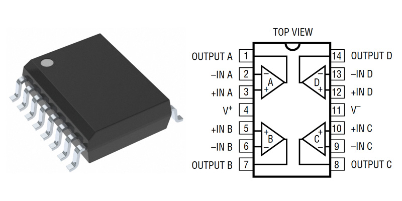
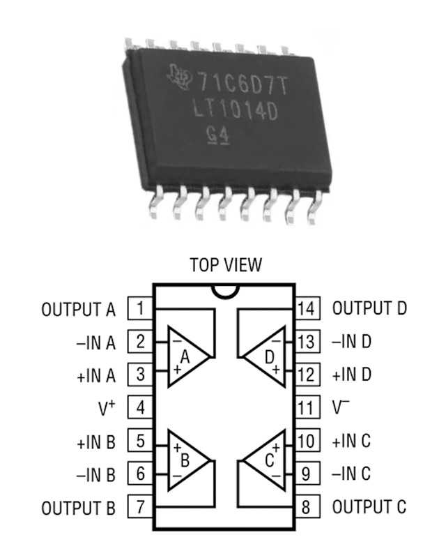
- Amplifier Type: General Purpose
- Number of Circuits: 4
- Output Type: -
- Package: 16-SOIC (0.295, 7.50mm Width)


FREE delivery for orders over HK$250.00

Quick response, quick quotaton

Flash shipment,no worries after sales

Original channel,guarantee of the authentic products
LT1014DSW


More Like This

74AHC1G04GW
Nexperia
74AHC1GU04GW
Nexperia

74HC27D
Nexperia
TC7S00FU
Toshiba
74LVC00APW
Nexperia

74HCT86D
Nexperia
74LVC1G11GW
Nexperia
HEF4071BT
Nexperia

74LVC1G02GV
Nexperia
HEF4070BT
Nexperia

MC14093BCP
onsemi
74HC32PW
Nexperia
Also Add to Cart

TLV2381IDBVR
Texas Instruments

853S01AKILF
Renesas Electronics America Inc

STR712FR2T6
STMicroelectronics

ADS1014IDGSR
Texas Instruments

STM32MP151AAA3T
STMicroelectronics

PIC16F877A-I/P
Microchip Technology

DS280DF810ABVT
Texas Instruments

ISL32435EIBZ-T
Renesas Electronics America Inc

AD9694BCPZ-500
Analog Devices Inc.

MC8640DTVJ1067NE
NXP USA Inc.

L6219DS
Allegro MicroSystems

BTS6163DAUMA1
Infineon Technologies
Related Products
74AHC1G04GW
Nexperia
74AHC1GU04GW
Nexperia
74HC27D
Nexperia
TC7S00FU
Toshiba
74LVC00APW
Nexperia
74HCT86D
Nexperia
74LVC1G11GW
Nexperia
HEF4071BT
Nexperia
74LVC1G02GV
Nexperia
HEF4070BT
Nexperia
MC14093BCP
onsemi
74HC32PW
Nexperia
74HC1G08GW
Nexperia
74AHC00D
Nexperia
74LVC1G86GW
Nexperia

HEF4093BP
NXP Semiconductors
74AUP1G08GW
Nexperia
74LVC1G02GW
Nexperia
TC4093BP
Toshiba
74AHC1G14GW
Nexperia
74LVC1G08GM
Nexperia
74AHCT125PW
Nexperia
TC7S08FU
Toshiba
74HC1G00GW
Nexperia
74AHC1G32GW
Nexperia
74AHC1G08GV
Nexperia
74LVC2G08DC
Nexperia
TC7SZ08FU
Toshiba
74HCT132D
Nexperia
74AHC1G09GW
Nexperia
Please send RFQ , we will respond immediately.

Please send RFQ , we will respond immediately.
Copyright © 2024 All Rights Reserved