Series VS Parallel Connections
Author:admin Date: 2025-01-20 06:22 Views:88
Introduction
Series and parallel connections are very simple ways of connecting circuits, and in life, we often see a combination of these two connections to form a mixed connection, and this article will explain in detail what the difference is between the two.
What is a Series Circuit?
The definition of a series circuit is that all the components are connected end-to-end and the current flows in this single path circuit. It’s like when you string a bead together with a piece of string.

What is a Parallel Connection?
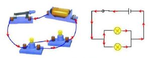
The definition of a parallel circuit is to connect the ends of all the components separately, with each component having a separate current path. It’s like having two separate strings strung on each bead.
Differences Between Series and Parallel Connections
There are different current distributions, etc. between series and parallel connections, and we use a table to show the difference between them in an easy-to-understand way.
| Characterization | Series Connection | Parallel Connection |
|---|---|---|
| Current | The current is the same throughout the circuit | Total current equals the sum of all branch currents |
| Voltage | The total voltage is equal to the sum of the voltage dividing each element | The voltage across each element is the same |
| Resistance | The total resistance is the sum of the resistance of each component | Total resistance is less than the resistance of the smallest individual component |
| Fault Impact | Failure of any one component will render the entire circuit inoperable. | Failure of a single component does not affect the operation of other components |
| Application Scenarios | Use in scenarios that require voltage summation, such as battery packs or small electronic experiments. | Ideal for scenarios that require reliability and independent operation, such as household circuits and industrial equipment. |
| Precautions | Focus on voltage stacking to avoid exceeding the maximum rated voltage of the device. | Consistency of connections to avoid damage or overheating of equipment due to high currents. |
Based on the above, we can know that their advantages and disadvantages are relative.
– For circuit connection, series circuit design is simple and easy to understand for scenarios that require voltage stacking, but it is less reliable, and if one component in the circuit is damaged, the whole circuit stops working.
– In contrast, parallel circuit design is relatively complex and is suitable for scenarios that require high reliability. Even if one component fails, the rest of the branch circuit can still operate normally, which is a great advantage in practical applications.
As an example:
If the whole house lights connected in series, that a bulb is bad, all the lights are not bright, but do not know which bulb is bad, must be one by one to check and repair.
But parallel connection is different, each bulb has an independent branch circuit, as long as which bulb is not bright, directly repair the bulb is not bright on the line, the other bulbs will not be affected.
Calculation Formula
In order to give you a better understanding of the difference between series and parallel, we have used a resistor as an example.
Series circuit

Suppose there are three resistors \( R_1 = 10\ \Omega \), \( R_2 = 20\ \Omega \), \( R_3 = 30\ \Omega \) in series with a total resistance of:
\(R_{\text{total}} = R_1 + R_2 + R_3 = 60\ \Omega\)
\(I = \frac{V_{\text{total}}}{R_{\text{total}}} = \frac{12\ \text{V}}{60\ \Omega} = 0.2\ \text{A}\)
\(V_1 = I \cdot R_1 = 0.2\ \text{A} \cdot 10\ \Omega = 2\ \text{V}\)
\(V_2 = I \cdot R_2 = 0.2\ \text{A} \cdot 20\ \Omega = 4\ \text{V}\)
\(V_3 = I \cdot R_3 = 0.2\ \text{A} \cdot 30\ \Omega = 6\ \text{V}\)
\(V_{\text{total}} = V_1 + V_2 + V_3\)
Parallel circuit

Suppose three resistors \( R_1 = 10\ \Omega \), \( R_2 = 20\ \Omega \), \( R_3 = 30\ \Omega \) are connected in parallel with a total resistance of:
\(\frac{1}{R_{\text{total}}} = \frac{1}{R_1} + \frac{1}{R_2} + \frac{1}{R_3}\)
\(\frac{1}{R_{\text{total}}} = 0.1 + 0.05 + 0.0333 \approx 0.1833\)
\(R_{\text{total}} \approx 5.45\ \Omega\)
\(V_1 = V_2 = V_3 = 12\ \text{V}\)
\(I_1 = \frac{V}{R_1} = \frac{12\ \text{V}}{10\ \Omega} = 1.2\ \text{A}\)
\(I_2 = \frac{V}{R_2} = \frac{12\ \text{V}}{20\ \Omega} = 0.6\ \text{A}\)
\(I_3 = \frac{V}{R_3} = \frac{12\ \text{V}}{30\ \Omega} = 0.4\ \text{A}\)
\(I_{\text{total}} = I_1 + I_2 + I_3\)