BC548 Transistor Pinout, Equivalent & Application Circuit
Author:admin Date: 2025-02-08 07:32 Views:174
Whether you are building an amplifier, designing a switching circuit, or working on an Arduino project, the BC548 NPN transistor is an important component in many electronic circuits. This article will introduce its pinout, principle of operation, technical specifications, common substitutes and typical application circuits to help you use the BC548 transistor more efficiently.
What is a BC548 Transistor?
The BC548 is an NPN-type bipolar junction transistor (BJT) that is often used in low power amplification, switching circuits and oscillators.
BC548 Transistor Pinout
The BC548 transistor pin consists of three terminals: collector (C), base (B), and emitter (E), which define the function and connection of the transistor in the circuit.
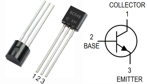
BC548 Pinout Diagram
BC548 Pin Configuration:
| Pin | Name | Description |
|---|---|---|
| 1 | Collector (C) | The current flows into the transistor through the collector. |
| 2 | Base (B) | The base controls the switching or amplification of the transistor. |
| 3 | Emitter (E) | The current flows out of the transistor through the emitter. |
BC548 Transistor Working
The principle of operation of the BC548 can be understood through a faucet analogy: the base electrode is like the switch of a faucet. It will control the amount of water flow, allowing a large amount of water to flow through the pipe (collector to emitter current). This means that a small change in base current can control the flow of a large current from the collector to the emitter, realizing the function of amplifying a signal or switching a current.
The operating mode of BC548 transistor is divided into amplification zone, saturation zone and cut-off zone:
Amplification region: the base current is forward biased with the emitter current, and the collector and base junction are reverse biased, the transistor works in the amplification state, and the collector current is proportional to the base current.
Saturation region: when the base current increases, the collector current approaches the maximum value, the transistor acts as a switch, and the current gain approaches zero.
Cut-off region: when the base current is zero, the collector current is zero, and the transistor is completely cut-off and non-conductive.

BC548 Transistor Cutoff State Diagram
BC548 Transistor Specifications
· Transistor Type: NPN Bipolar Junction Transistor (BJT)
· Package: TO-92 (3-lead through-hole package)
· Operating Temperature Range: -55°C to +150°C
· Collector Capacitance (Cc): 4pF
· Polarity: Emitter-Base-Collector
· Maximum Collector-Emitter Voltage (V_CEO): 30 V
· Maximum Collector-Base Voltage (V_CBO): 30 V
· Maximum Emitter-Base Voltage (V_EBO): 5 V
· Maximum Collector Current (I_C): 100 mA
· Maximum Power Dissipation (P_tot): 500 mW (0.5 W)
· Transition Frequency (f_T): 250 MHz (typical)
· Base-Emitter Threshold Voltage (V_BE): Typically 0.7 V at I_C = 10 mA
· DC Gain (hFE): Ranges from 110 to 800, depending on the specific version (BC548A, BC548B, or BC548C).
BC548 Datasheet PDF Download
BC548 Transistor Applications Circuit
1. Switching Circuit
The BC548 can be used as a low power switch to control low power loads.
Application Example: LED Switching Circuit
Circuit Principle
The positive terminal of the power supply is connected to the LED through a current limiting resistor, and the other end of the LED is connected to the collector of the BC548.
The base is connected to the control signal source through a current limiting resistor, and the emitter is grounded.
When the base current is sufficient, the transistor conducts and the LED lights up.
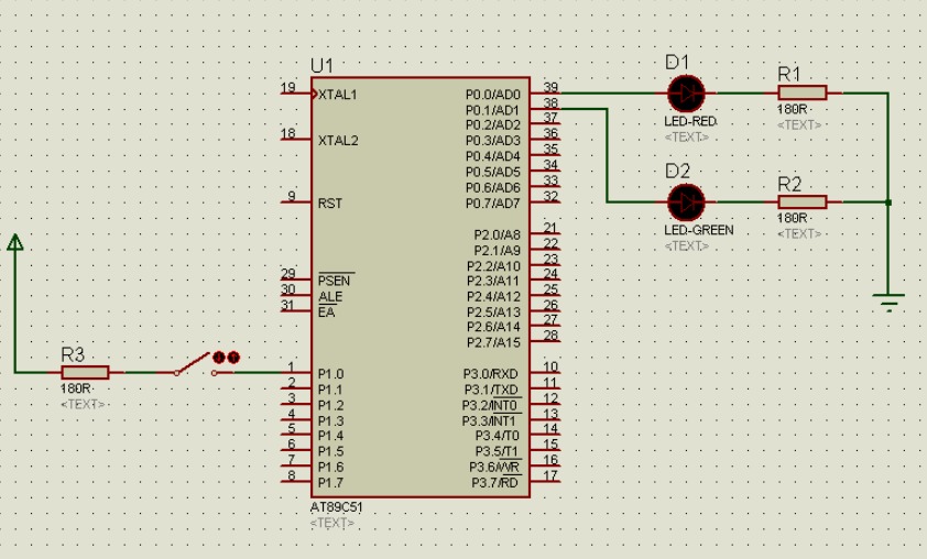
BC548 Transistor LED Switching Circuit Diagram
2. Amplifier Circuit
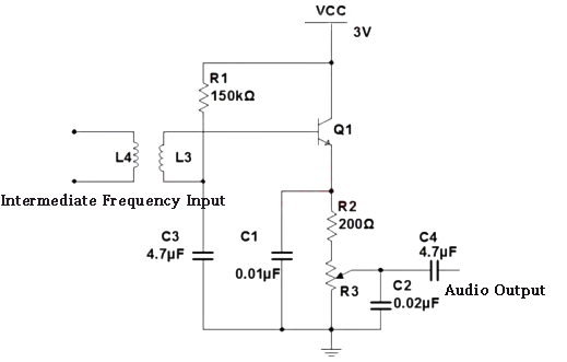
The BC548 can be used to amplify weak audio signals. Common applications include preamplifiers, tone controllers, or small audio amplifiers.
Application Example: Audio Amplifier
Circuit Principle
The input signal is applied to the base through a coupling capacitor.
The base current controls the collector current to amplify the signal.
The collector is connected to the load and the amplified signal is output from the collector, and the emitter is grounded.

BC548 Audio Amplifier Circuit Diagram
3. Oscillator Circuits
The BC548 is commonly used to build oscillator circuits for low-frequency applications such as Morse code generators, timers, and clock circuits.
Application Example: Morse Code Oscillator
Circuit Principle
The RC network provides feedback to form self-excited oscillation and couples the output signal to the base.
The oscillation frequency is determined by the RC parameters.
A capacitor couples the signal to a load (e.g., speaker) to generate a signal of the desired specific frequency.

BC548 Morse Code Oscillator Circuit Diagram
4. Water Level Indicator Circuit
The BC548 can be used to detect changes in water level and indicate them via LEDs or relays.
Application example: Water level indicator
Circuit principle
The sensor is connected to the base electrode, which controls the conduction or cut-off of the transistor.
When on, current flows through the collector and emitter, driving an LED or relay.

BC548 Water Level Indicator Circuit Diagram
5. BC548 Tone Control Circuit
The BC548 is also used in audio conditioning circuits, especially in bass and treble controls, to optimize sound quality by adjusting the frequency response.
Application Example: Bass and Treble Conditioners
– Bass Adjustment: Enhances low frequencies and attenuates high frequencies through a low-pass filter (resistor + large capacitor).
– Treble control: low frequencies are filtered out and high frequencies are preserved by a high pass filter (resistor + small capacitor).
Circuit Principle
A potentiometer is used to adjust the frequency response of the filter to selectively amplify or attenuate signals in a particular frequency band.
The BC548 amplifies the filtered signal and drives the load output.

BC548 Bass Circuit Diagram
BC548 Treble Circuit Diagram
BC548 Transistor Equivalent and Alternative
PNP Type Complementary Models: BC558, BC559
Alternatives and Equivalents: BC547, BC549, 2N2222, 2N3904, 2N4401, BC337
SMD equivalents: BC847, BC847W, BC850, BC850W (for surface mount)
– BC547 VS BC548: The difference is very small, mainly in noise performance. BC547 and BC548 can be used interchangeably in low power circuits.
– BC549 VS BC548 : BC549 is suitable for high voltage and high frequency circuits, while BC548 is more suitable for low voltage, low power applications.
– 2N2222 VS BC548 : The 2N2222 can handle higher currents, while the BC548 focuses on small signal, low current applications.
– 2N3904 VS BC548 : The 2N3904 has a high frequency response and is suitable for high frequency circuits, while the BC548 is more suitable for applications with low frequency requirements.
– BC108 VS BC548: The BC108 is an older model and has been replaced by the BC548, which is more widely used in modern circuits.
– BC337 VS BC548: The BC337 supports larger current applications, while the BC548 focuses on low-power signal amplification.
Please send RFQ , we will respond immediately.
Frequently Asked Questions
1. BC548 NPN or PNP?
NPN bipolar Junction Transistor (BJT).
2. How to identify terminals of BC548 Transistor?
It’s simple: From the front of the transistor, the flat side faces you. The left pin is the collector, the middle pin is the base, and the right pin is the emitter.
3. How to Test if a BC548 Transistor is Working?
To check if the BC548 transistor is working, use a multimeter to measure the resistance between the base and emitter. If the transistor is working properly, it should show a smaller resistance when forward biased.


